-
-
March 29, 2021 at 3:20 pm
MiguelGuerra
SubscriberHello everybody.
I would like to ask you some help because I have been stuck for a few weeks with a simulation.
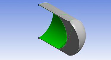
I have this geometry; it is half of the top of a hemispherical piston. The green walls correspond to the piston, so they move in the simulation.
March 30, 2021 at 5:52 pmSurya Deb
Ansys EmployeeHello, nSince you have tested it thoroughly, I believe you have already checked it. nBut can you please make sure to use the Local Mesh settings for Remeshing instead of Global values. You will get the local info by using Mesh Scale Info button. Then use those values or values close to them for the Min/Max lengths scales.nYou mesh might be getting very skewed before it gets remeshed. Also make sure to frequently do the remeshing if the deformation is significant.nRegards,nSDnMarch 30, 2021 at 6:41 pmSubscriberHello, Since you have tested it thoroughly, I believe you have already checked it. But can you please make sure to use the Local Mesh settings for Remeshing instead of Global values. You will get the local info by using "Mesh Scale Info" button. Then use those values or values close to them for the Min/Max lengths scales.You mesh might be getting very skewed before it gets remeshed. Also make sure to frequently do the remeshing if the deformation is significant.Regards,SD/forum/discussion/comment/113342#Comment_113342
Hello sdeb.nNormally when I go to the remeshing mesh method settings I enable local cell and local face, then I click 'Use Defaults' for the parameters and in 'Size Remeshing Interval' I put 1 interval. nFor more information, in this simulation, the walls are moving 11.3 mm in 0.15 s (reaches top) and then 22.6 mm backward in the next 0.45 s (reaches bot) and it goes again 22.6 mm to top (piston movement). The velocity varies in a sinusoidal function (UDF). If the wall moves too fast from one time step to another, it causes the negative cell volume, isn't it? nWhich values for cell skewness and face skewness should I consider as maximums?nIs it good to use the layering method with a tetrahedral mesh?nHere is a pic of the mesh.n Thank you for your attention.nn
March 30, 2021 at 6:57 pmAnsys EmployeeHello, nPlease see embedded image on what I meant for Mesh Scale Info. Also, dynamic layering has a few limitations with mesh type like hexahedral elements need to be used. Please check this link : https://ansyshelp.ansys.com/account/secured?returnurl=/Views/Secured/corp/v195/flu_ug/flu_ug_dynam_mesh_update.html%23flu_ug_dynam_layer_meth.nYes, if you can split your domain avoiding the limitations of dynamic layering, then it will be easier and faster and more stable approach than remeshing.n
Thank you for your attention.nn
March 30, 2021 at 6:57 pmAnsys EmployeeHello, nPlease see embedded image on what I meant for Mesh Scale Info. Also, dynamic layering has a few limitations with mesh type like hexahedral elements need to be used. Please check this link : https://ansyshelp.ansys.com/account/secured?returnurl=/Views/Secured/corp/v195/flu_ug/flu_ug_dynam_mesh_update.html%23flu_ug_dynam_layer_meth.nYes, if you can split your domain avoiding the limitations of dynamic layering, then it will be easier and faster and more stable approach than remeshing.n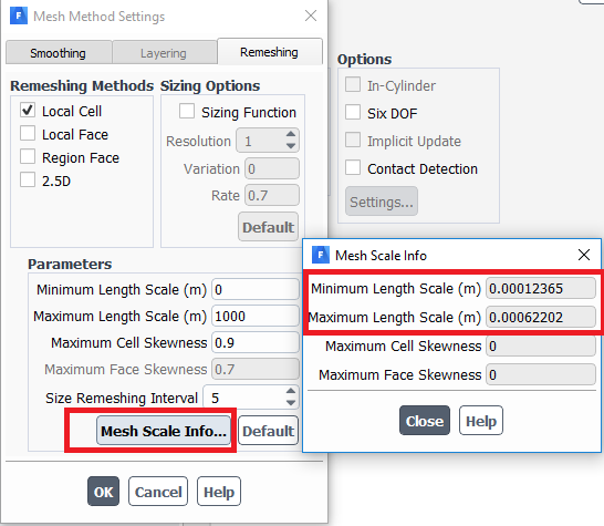 n
March 31, 2021 at 2:43 am
n
March 31, 2021 at 2:43 amYasserSelima
SubscriberMake the minimum length scale zero and increase the interval. Use the same maximum appear in the mesh scale info. Also make sure your time step is much lower than ( minimum length scale/max_wall_velocity) nMarch 31, 2021 at 3:13 pmSubscriberMake the minimum length scale zero and increase the interval. Use the same maximum appear in the mesh scale info. Also make sure your time step is much lower than ( minimum length scale/max_wall_velocity)/forum/discussion/comment/113389#Comment_113389
Hello Yasser,nI tried your answer but I still got the negative cell volume error. Here is what I have done, can you take a quick look at it in case you see the mistake?n1st I mesh the model and create the named selections in the ansys meshing bench and I export it as .mshn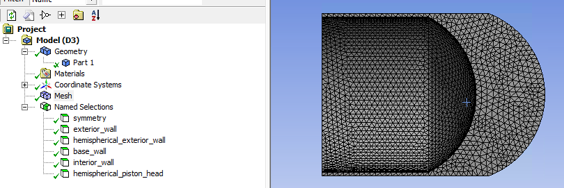 2nd I read and check the mesh in fluent. Then I go to Boundary Conditions and Cell Zone Conditions to make sure it is right. n
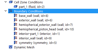 3rd Mesh Method Settings: I enable Smoothing and Remeshing. For Smoothing I enable Spring with Constant Factor=0. In remeshing I do what you said.n
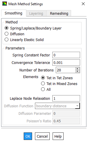
 4th Dynamic Mesh Zones. I compiled the UDF and create the zones. npiston head: rigid body and select the udf file. In meshing options I let it as default (cell height 0 m)ninterior, symmetry and interior wall: deforming, and in the zone parameters I only change the maximum lenght scale as zone scale info.n
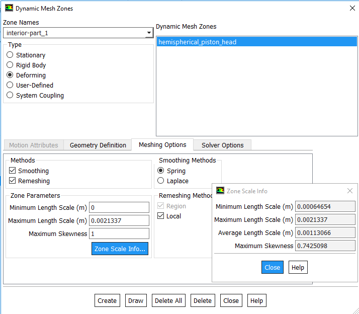 fot the base and exterior walls I don't create Dynamic Mesh Zones, should I create them as stationary?n
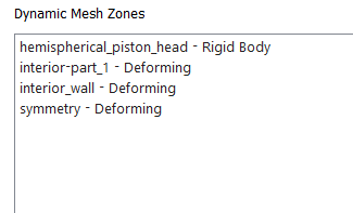 5th Display Zone Motion: it moves as I want. n6th Preview Mess Motion:n In the Mesh Method Settings, for Remeshing, the minimum length scale is 0.00048793 m = 0.48793 mm. With the UDF equation I have that the max velocity is 118.33 mm/s so the time step should be lower than 0.48793/118.33 = 0.004123 s. I take 0.001 s. n
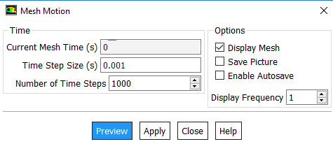 And when I preview it fails at time step 12. nAt time step 11 I get this message: n Dynamic Mesh Statistics:n Minimum Volume = 1.10750e-12n Maximum Volume = 9.44725e-10n Maximum Cell Skew = 1.00000e+00 (cell zone 2) (it is the interior)n Warning: maximum cell skewness exceeds 0.95.n Minimum Orthogonal Quality = 5.57139e-10 (cell zone 2) (interior)n Warning: minimum orthogonal quality less than 0.05.n Maximum Face Skew = 9.99545e-01 (face zone 5) (symmetry wall)n Warning: maximum face skewness exceeds 0.95.nAt time step 12:n Smoothing partition boundaries...n WARNING: 2 cells with non-positive volume detected.n Error at host: Update-Dynamic-Mesh failed. Negative cell volume detected.nnDo you see any mistake? Am I doing something wrong?nHow can I use the Cell Registers to see the cells with negative volume? I read that it is with Filed Variable but it is locked:n
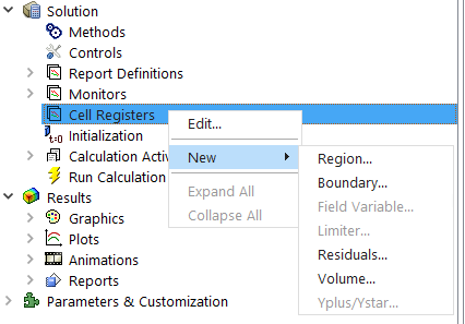 nThank you for your help and attention and sorry for the inconvenience.n
March 31, 2021 at 3:36 pm
nThank you for your help and attention and sorry for the inconvenience.n
March 31, 2021 at 3:36 pmgowtham326
SubscriberI think you need atleast 2 elements between your inner and outer wall. You need to initialize first for field variables to activate in cell register.nMarch 31, 2021 at 4:34 pmSubscriberI think you need atleast 2 elements between your inner and outer wall. You need to initialize first for "field variables" to activate in cell register./forum/discussion/comment/113519#Comment_113519
Hi gowtahm326, nthanks for your answer. I have prepared this mesh quickly to test your advice.n
 nI followed the same steps, I got a new minimum lenght scale = 0.00017075 m so the new time step size is 0.00144299. I took 0.0005 s at time step size but it still failed with negative cell volume error at time step 47 (at least it doubled the simulation time). I think you got a point, so I will try to remesh the model with more cells between the walls and reduce the number of elements in the hemispherical part (to reduce the computational cost) while I wait for more answers/help. nAlso, how do I initialize first for 'field variables'?n
March 31, 2021 at 4:40 pmSubscriberI agree with you need two elements at least .. I would add to this, use diffusion instead of spring under smoothing.nApril 1, 2021 at 12:54 pmSubscriber
nI followed the same steps, I got a new minimum lenght scale = 0.00017075 m so the new time step size is 0.00144299. I took 0.0005 s at time step size but it still failed with negative cell volume error at time step 47 (at least it doubled the simulation time). I think you got a point, so I will try to remesh the model with more cells between the walls and reduce the number of elements in the hemispherical part (to reduce the computational cost) while I wait for more answers/help. nAlso, how do I initialize first for 'field variables'?n
March 31, 2021 at 4:40 pmSubscriberI agree with you need two elements at least .. I would add to this, use diffusion instead of spring under smoothing.nApril 1, 2021 at 12:54 pmSubscriberhttps://us.v-cdn.net/6032193/uploads/2HO7ESHVOV7R/image.pngI followed the same steps, I got a new minimum lenght scale = 0.00017075 m so the new time step size is 0.00144299. I took 0.0005 s at time step size but it still failed with negative cell volume error at time step 47 (at least it doubled the simulation time). I think you got a point, so I will try to remesh the model with more cells between the walls and reduce the number of elements in the hemispherical part (to reduce the computational cost) while I wait for more answers/help. Also, how do I initialize first for "field variables"?/forum/discussion/comment/113538#Comment_113538
Hello,nIts difficult to tell until you see where the negative cells are. Try thesenBefore you hit 'run calculation' there is 'initialization' under 'Monitors' section. Choose Hybrid and 10 as no of Iterations. After this you can go to field variables and try,nUnder results, go to mesh and create new mesh plane before running calculation. After run your calculation - go back to mesh plane right click and display. This should show where the negative cells are .nCheers.nApril 2, 2021 at 3:50 pmSubscriberI agree with @gowtham326 , you need two elements at least .. I would add to this, use diffusion instead of spring under smoothing./forum/discussion/comment/113539#Comment_113539
Hi Yasser, I´ve tried this.nFirst I changed the geometry by removing the cylindrical internal wall because I think it is better to simulate that part with hexa mesh and layering with an interface mesh with the hemispherical part. So here is the new geometry and mesh I'm trying.n
 In the Mesh Method Settings I use this: n
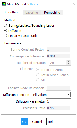
 And then I create the Dynamic Mesh Zones: n
 For the time step size in Mesh Motion I take 0.0005 s. And it goes great until it almost reach the top because the negative cell volume comes. The piston reaches the top at 0.15 s and it fails at 0.1335 s. n
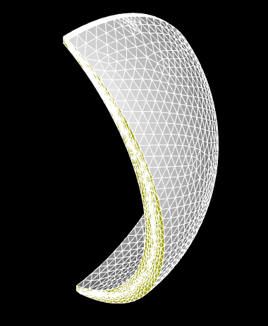 I think that the error is from this part.n
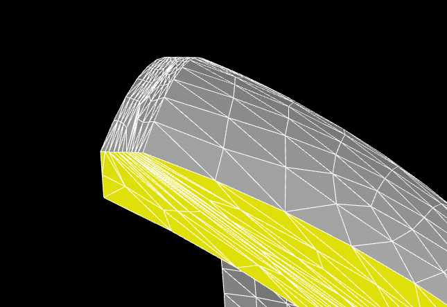 The exterior wall should dissapear whe the piston reaches top and then appear again when it comes back. Is there a way to make it possible? With layering technique and hexa/prism mesh I did this in other geometry but I don´t how to do this with tetra mesh. For the dynamic mesh zone of the wall I have this. n
 Do you have any idea?nThank you for your help and attention.nn
April 3, 2021 at 2:36 pmSubscriberI am not sure what is wrong ... there is no re-meshing happening! decrease the intervals to 3 or 4 ... hopefully this worksnViewing 11 reply threads
Do you have any idea?nThank you for your help and attention.nn
April 3, 2021 at 2:36 pmSubscriberI am not sure what is wrong ... there is no re-meshing happening! decrease the intervals to 3 or 4 ... hopefully this worksnViewing 11 reply threads- The topic ‘Dynamic Mesh problem, can’t avoid negative cell volume detected’ is closed to new replies.
Innovation Space Trending discussions
 Top Contributors
-
peteroznewman
 5844
5844 -
scabo
 1906
1906 -
Dennis Chen
 1420
1420 -
javat33489
 1305
1305 -
Shyam Prasad V Atri
1021
Top Rated Tags
© 2026 Copyright ANSYS, Inc. All rights reserved.
Ansys does not support the usage of unauthorized Ansys software. Please visit www.ansys.com to obtain an official distribution.
-
Ansys Assistant will be unavailable on the Learning Forum starting January 30. An upgraded version is coming soon. We apologize for any inconvenience and appreciate your patience. Stay tuned for updates.