-
-
July 30, 2023 at 12:37 pm
Osama Maddani
Subscriber
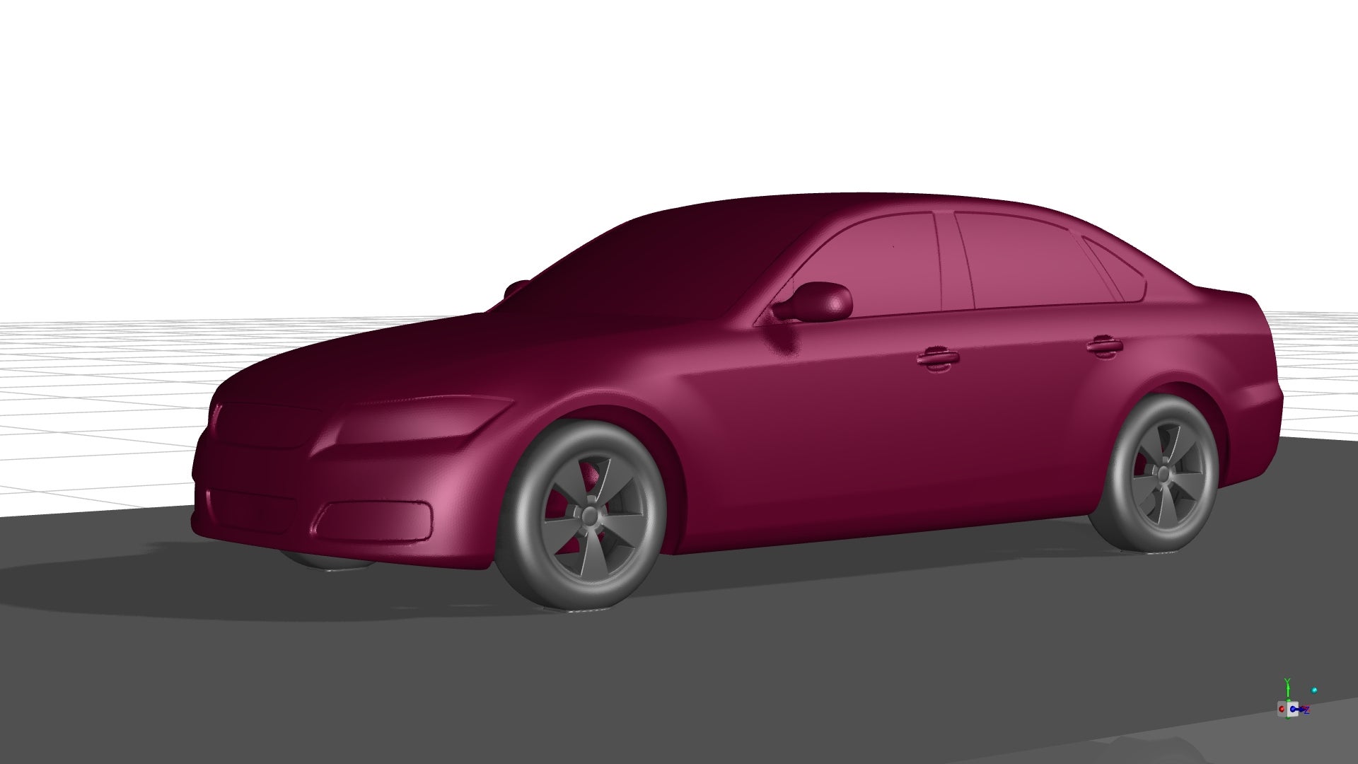
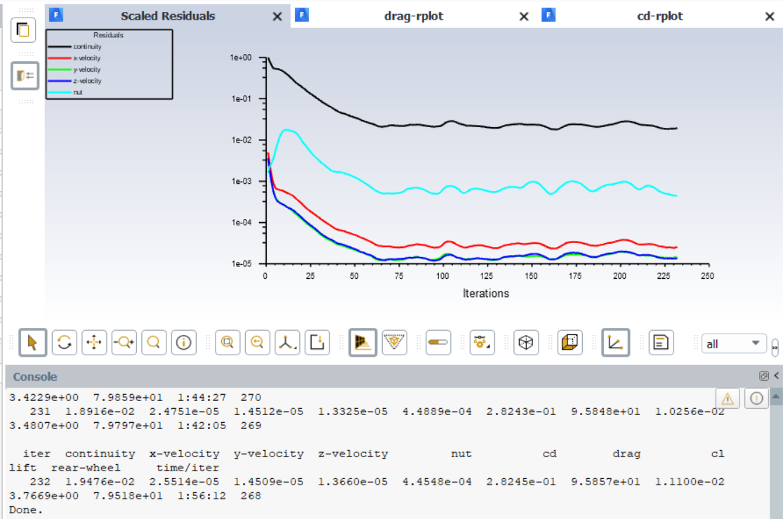
Please help I am getting a higher Cd value using Ansys fluent than the actual Cd value that is stated in the research paper by the Technical University of Munich as the results of wind tunnel experiments. for the NSwMwW (Notch back Smooth underbody with Mirrors with Wheels) configuration with Ground simulation I am getting 0.282 value in contrary to the stated value of 0.246. I have made got the geumoetry from the TUM website, prepared it Ansys spacelaim with an enclosure of 3m in front of the car and 5 m behind the car 2.5 m above, right and left of the car, which gives a blockage ratio of 12.7%. the Mesh is made in Fluent meshing with 4.23 million cells using a poly-hexcore meshing method, and a uniform boundary layer comprised of 5 layers with a first cell height of 0.001m and a 1.25 growth ratio. In Fluent the turbulence model is the Spalart almarrs model with default settings, the boundary conditions are 0shear wall for the sky summetry bc for the sidewalls and moving wall at 16m/s for the road, the wheels are rotating walls wiht thier respective axis location and a rotional velocity of ω=v/r, and pressure outlet or the outlet and a velocity inlet with a velocity of 16m/s which gives the Re number of 4.87e6 for a reference length of 4.6m, that the experiments were conducted at. Using a coupled pressure velocity coupling method and second order upwind scheme. the frontal area is calculated using projected areas with a minimum feature length of 0.001 m . residuals are set to 1e-5 but not all of them reach it here's how the residuals look like:
-
July 31, 2023 at 7:26 am
Atharva Nagarkar
Ansys EmployeeHello,
Ansys has recently published a free course on simulating the external aerodynamic analysis of a car. Please find the link below. You can find the right guidance related to meshing and solver setup from it. It is likely that the boundary layer is not resolved properly in your case and that is giving an error in the Cd value. Also, Spallart Almaras is not the best choice of turbulence model for this case. For details on tubulence modeling, please refer the course mentioned below.
CFD Simulation of an FSAE Car | Ansys Innovation Courses
Turbulence Modeling in Ansys Fluent | Ansys Innovation Courses
If you are not able to access the link, please refer to this forum discussion: Using Help with links (ansys.com).
Thanks!
-
August 6, 2023 at 6:49 pm
Osama Maddani
SubscriberThank you Mr.Nagarkar
I have looked up the tutorial and didn't follow it exactly but it went a long way in helping me improve my accuracy, 1. I increased the domain extent so that now i have ablockage ratio of arounf 3% and i have around 4 cars' length behind the car, but i increased the max cell size to keep the cell count down . 2. I changed the model to the one recommended by the course GEKO and changed the CSEP to 1. 3. I used rotating wall bc and didnt use the rotating reference frames for the wheels.
with all of these modifications i improved my Cd percentage error down to a value of only 2.5%, which is acceptable.
-
-
- The topic ‘DrivAer validation car model’ is closed to new replies.
-
3472
-
1057
-
1051
-
934
-
902
© 2025 Copyright ANSYS, Inc. All rights reserved.