-
-
December 19, 2024 at 11:06 amkrystof.toporSubscriber
Hi everyone,
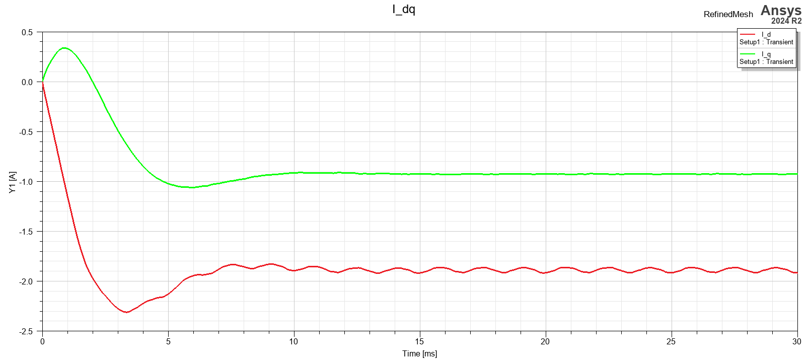
Are the automatically generated plots with DQ quantities (DQ current, voltages, etc..) in model created via RMxprt "Create Maxwell Design" correctly aligned? I was playing with AFPM examples and the DQ currents in the Maxwell model seem wrongly transformed. I would expect Q current to be positive in motoric mode.
I couldn't find anything on how is the model generated in the documentation on anywhere else. And when trying to manually calculate the aligment angle, aligning N magnet with Phase A, I got different results.
-
January 28, 2025 at 6:58 pmMiranda HourihanAnsys EmployeeHi, yes, you are correct, Iq is not right here. Please create a new report -> Domain:Transient D-Q ->Machine Options: Number of poles in the machine 0(Update this and OK) -> Winding->I(q-axis).
-
Viewing 1 reply thread
- You must be logged in to reply to this topic.
Ansys Innovation Space
Trending discussions
- HFSS Incident Plane Wave excitement mode
- How to calculate eddy and hysteresis losses of the core?
- Ansys Maxwell 3D – eddy current
- Simulation of capacitor combining eddy currents with displacement currents
- dq graph non-conformity
- Simplorer+Maxwell Cosimulation results and Maxwell results mismatch
- Parametrizing coil “terminals” with coil geometry
- Maxwell circuit – PWM
- Plotting Ex, Ey and Ez in vector forms individually
- Calculating E-field tangential to a 2D resonant structure on a sapphire chip
Top Contributors
-
1882
-
802
-
599
-
591
-
366
Top Rated Tags
© 2025 Copyright ANSYS, Inc. All rights reserved.
Ansys does not support the usage of unauthorized Ansys software. Please visit www.ansys.com to obtain an official distribution.