-
-
October 23, 2024 at 5:02 pm
bpedar
SubscriberHello,
I have modeled a 14 pole rotor rotating at 500 mechanical RPM in the condition of no excitation in the windings. Then created the following output variables to change the coordinate system from 3 phase to alpha_beta for the stationary and dq for rotating. Expecting to see constant values in dq frame.Â
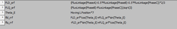
the FLD_srf is flux linkage in alpha and FLQ_srf is the flux linkage in beta coordinates and the fld and flq in rrf are in dq coordinates. the number 7 is multiplied to mechanical angle to give back the electrical angle. the graphs recieved are:Â
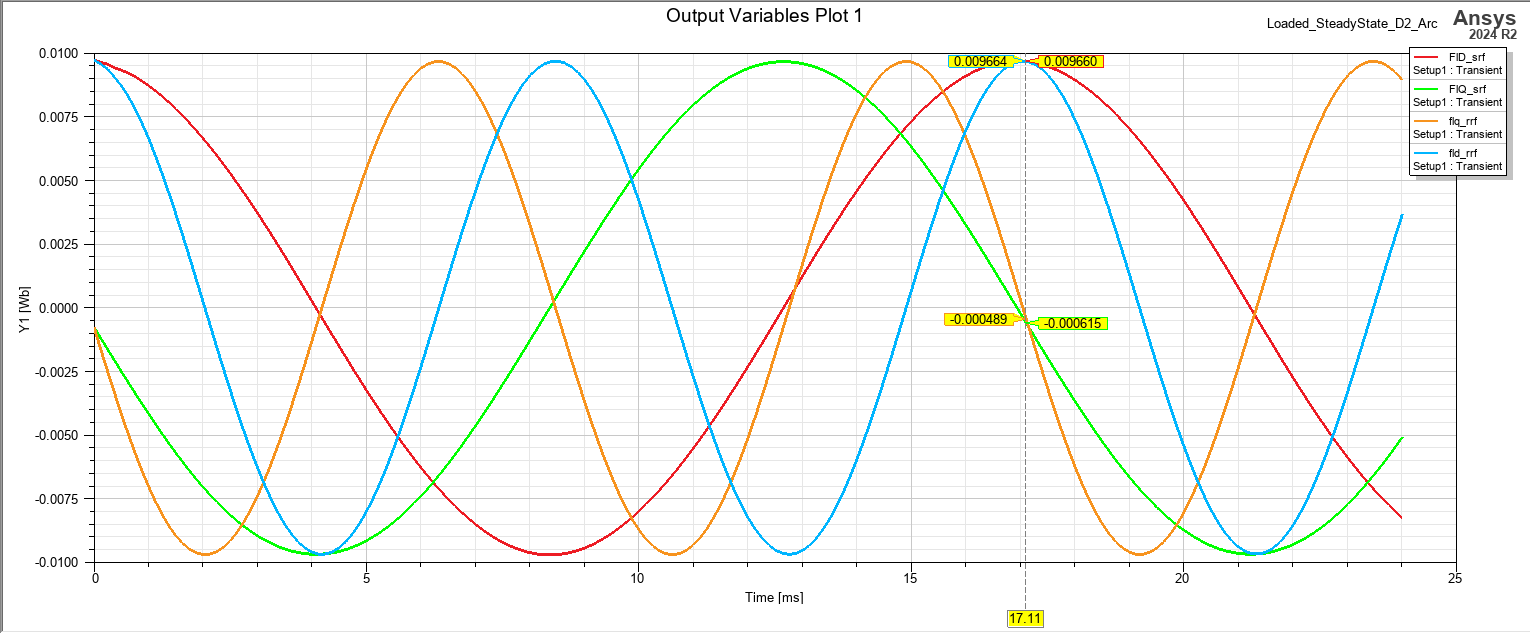
as can be seen the alpha beta coordiante are as expected but dq is not and is producing a wave with twice the frequency of electrical. Appreciate anyone helping in solving this issue.Â
-
November 19, 2024 at 4:17 pm
Tamami Yamanaka
Ansys EmployeeHello,
Moving1.Position, cos(Theta_E) and sin(Theta_E) against time in the XY plot to check that they show the expected periodicity and linear behaviour.
-
- You must be logged in to reply to this topic.
- Ansys Maxwell 3D – eddy current
- Plotting Ex, Ey and Ez in vector forms individually
- Maxwell circuit – PWM
- Compute near field simulation with current
- Ansys-MATLAB Co-Simulation
- Simplorer+Maxwell Cosimulation results and Maxwell results mismatch
- Y wiring method and the start and end points of winding.
- Ansys Resonance simulatioin error
- How does Ansys Twin Builder implement different simulation steps for subcircuits
- Calculating E-field tangential to a 2D resonant structure on a sapphire chip
-
2457
-
931
-
599
-
591
-
586
© 2025 Copyright ANSYS, Inc. All rights reserved.