TAGGED: iterative-solver, sparse-direct-solver
-
-
August 6, 2021 at 6:55 am
Rameez_ul_Haq
SubscriberI know that for linear problems, I can directly make use of either direct or iterative solver. But for a non-linear problems, can direct solvers be used, or I have to be dependent upon iterative solvers only?
August 7, 2021 at 12:14 ampeteroznewman
SubscriberDirect solvers can always be used and are generally the better choice for non-linear problems.
Iterative solvers can be a benefit when there is a lot of nodes, because they take less memory.
August 7, 2021 at 7:32 pmRameez_ul_Haq
Subscriber,but how can Newton-Rapshon and direct solver go hand in hand? Since non-linearity is involved, there needs to be iterations made using the Newton-Raphson (where the displacements are guessed and then iterations proceed). But the direct solver uses a LU decomposition within the stiffness matrix to solve for the displacements without guessing of the displacements. This thing kind of boggles me.
August 7, 2021 at 8:25 pmpeteroznewman
SubscriberThere are two levels of iteration when an iterative solver is working on a nonlinear problem. To avoid confusion, let's call the iterative solver the PRECONDITIONED CONJUGATE GRADIENT SOLVER (PCG)
Both direct and PCG solvers can compute a nonlinear analysis. Nonlinear means that the stiffness matrix equation is solved once, then a convergence evaluation is made to decide if the nonlinear system has converged. If not another solution of the stiffness matrix equation is made with updated values. Each time the stiffness matrix is solved, that is called an iteration. After an iteration meets the convergence criteria, that is called a substep and the load is incremented and the next substep can begin with the first iteration.
As you note, the direct solver, also called the SPARSE SOLVER, uses LU decomposition to solve the stiffness matrix equation.
The PCG solver uses an iterative algorithm to solve the stiffness matrix equation. In a linear analysis, that is done once. In a nonlinear analysis, that is done for every dot on the N-R Convergence plot (every nonlinear iteration).
August 9, 2021 at 11:46 amRameez_ul_Haq
Subscriber,understood. Thank you for answering. I was thinking that since stiffness matrix itself depends on the response of the nodal displacements, so I cannot conduct a LU decomposition on it. But apparently the LU decomposition can also work on a non-linear set of equations where the stiffness matrix itself is a funtion of the nodal displacements. But still I am slightly confused that if the convergence is not achieved for a specific iteration for a specific time step, then still there are no guesses made (since LU decomposition, by theory and its name, doesn't involve any guesses)? If not, then how does the iterations proceed?
And also, as you have mentioned that the Iterative solver requires only one iteration to converge at t = 1 sec i.e. the final time step for a linear analysis. So is it possible that the solution doesn't converge at that time step ? What measures can be taken to make the linear analysis converge at the one and only i.e. final time step?
August 10, 2021 at 2:13 pmRameez_ul_Haq
Subscriber,would be extremely glad if you could reply to this one as well :)
August 11, 2021 at 2:56 ampeteroznewman
SubscriberI was thinking that since stiffness matrix itself depends on the response of the nodal displacements
Stiffness matrix for a single solve does not depend on the response of the nodal displacements. Stiffness matrix [K] is assembled from the elements that connect the nodes in their current location. Nodal deformation {u} are the unknowns, applied forces {F} are known. The matrix equation [K]{u}={F} is solved for the unknown nodal deformations.
But apparently the LU decomposition can also work on a non-linear set of equations where the stiffness matrix itself is a function of the nodal displacements.
The stiffness matrix for a single solve is not a function of nodal displacements. Solving [K]{u}={F} can be done using the Sparse direct method or PCG iterative method.
In a nonlinear problem, on each iteration, the matrix equations [K]{u}={F} are linear in that iteration. It is only after the deformed nodal values from that one iteration are added to the current nodal locations to get the new nodal locations that items that were held constant for that one iteration can pick up new values for the next iteration. That is where the nonlinearity occurs. The stiffness matrix can change between iterations because of a material nonlinearity. Contact nonlinearity can change the {F} vector between iterations.
And also, as you have mentioned that the Iterative solver requires only one iteration to converge at t = 1 sec i.e. the final time step for a linear analysis.
I did not say that the PCG iterative solver requires only one internal iteration to converge. What I said was that in a linear analysis, the matrix equation [K]{u}={F} is solved only once, using either the PCG iterative or direct solver.
Again, there is confusion between convergence of a single PCG iterative solver solving [K]{u}={F} one time, and convergence of a nonlinear model that requires multiple solves of the matrix equation [K]{u}={F}.
The PCG iterative solver might take tens or hundreds of internal iterations to solve [K]{u}={F} one time. It is possible that the internal PCG iteration fails to converge. That is an internal convergence for the PCG solver doing a single matrix solve and has nothing to do with the nonlinear model that does many matrix solves and has a completely separate external convergence criteria of results between solves.
In a linear analysis, the matrix equation [K]{u}={F} is solved only once. If the matrix is singular, there is no solution and both the direct and PCG iterative solvers will fail. A common reason for this is insufficient constraints to prevent rigid body motion.
In a nonlinear analysis the matrix equation [K]{u}={F} is solved over and over, updating the nodal coordinates, which affects the stiffness matrix and the force vector. When the updated system of equations is available, the equilibrium of the forces in the system of equations can be checked. It the equilibrium is sufficiently close to zero, that iteration is called converged. If the equilibrium of forces is not sufficiently close to zero, then another solution is done, which is the next iteration.
August 11, 2021 at 9:11 amRameez_ul_Haq
Subscriber,such a simple and straight forward explanation. Thank you for that.
"The PCG iterative solver might take tens or hundreds ofinternaliterations to solve [K]{u}={F} one time. It is possible that the internal PCG iteration fails to converge." Yes, that is what I was asking actually. How do we know that internal PCG iterations have failed to converge? I mean how to diagnose it? What measures should be taken to solve this problem?
Moreover, you mentioned, "Nodal deformation {u} are the unknowns, applied forces {F} are known. The matrix equation [K]{u}={F} is solved for the unknown nodal deformations." If this is the case, then I think in non-linear analysis, we should be expecting the force/moment/displacement convergence curve (i.e. the magenta curves) to always be equal to zero. Since we are already making use of the external forces to actually calculate the nodal displacements. So there shouldn't exist any difference between the [F] (external force) and [K][U]. What would you say on this?
Plus, I just want to confirm one more thing. So why is the static structural an implicit solver? I mean we are applying the force at a specific iteration of a certain time step, the stiffness matrix is already know at that specific iteration of that certain time step (being assembled from the already calculated nodal displacements from previous iteration) and we just calculate the nodal displacements from here for the next iteration. Simple. Why does it make the analysis implicit?
August 11, 2021 at 12:52 pmpeteroznewman
SubscriberYou know that the PCG iteration has failed to converge because there is an error in the Solution Output file. The corrective action is to switch the the Direct solver.
In a linear analysis, there is a check called back substitution. If you put the calculated nodal displacements back into the matrix equation that uses the applied forces, the answer should be very, very close to zero, like smaller than 1E-9. In NASTRAN, that number is called Epsilon and is a measure of the numerical quality of the matrix solve. If the value comes out to be large, like bigger than 1E-6, then there is probably something wrong with the model. I once had a model that had Epsilon value larger than 0.1 and the results were total garbage. If there was more wrong with the model, the matrix solution would have failed completely with a zero pivot error and it would be a FATAL error.
In a nonlinear analysis, the solution is used to compute the internal forces, and those are compared with the applied forces and the difference compared with the convergence criteria. The graph below is from this discussion: /forum/index.php?p=/discussion/22968/why-do-the-stresses-increase-near-the-supports
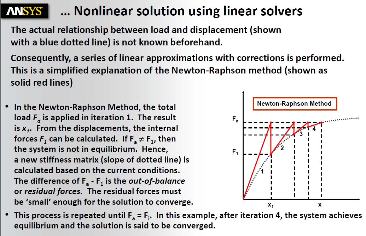 Implicit vs Explicit refers to solving dynamics problems where there is a time integration. Transient Structural uses Implicit methods where large time steps can be used but the matrix equation has to be solved multiple times (iterations) to get the system into equilibrium at each time step. Explicit Dynamics uses Explicit methods where very, very small time steps are used but there is no requirement to show equilibrium at each time step. The solver simply applies the correction needed at the next time step. In that way, the system remains in equilibrium over time.
August 11, 2021 at 3:04 pmRameez_ul_Haq
Subscriber,for the picture that you have re-shared here, I would like to ask something. Since displacements are already calculated from the External forces, and then we are calculating the internal forces from the resulting nodal displacements, but I don't see a reason why the internal calculated forces will not be equal to the externally applied forces. Ofcourse, this might be related to the numerical nature of the FEA softwares but where exactly it makes an approximation so that the internal forces don't become equal to the external forces (or the difference doesn't come down the defined limit). As far as a I see it, there is a straight forward way. Calculate the nodal displacements from external forces, and then re-calculate the internal forces. But why would these internal forces be different from the external forces, I couldn't grasp it.
If I am using a PCG solver, then I can assume that there might be some approximations made and internal forces are not equal to the external forces. But for a non-linear analysis where Direct solver is utilized, where no approximations are made at all (I believe) and there is a simple LU decomposition, why won't it make the internal forces become equal to the external one on the first iteration?
August 11, 2021 at 4:26 pmpeteroznewman
SubscriberYou missed the sentence starting with Hence...
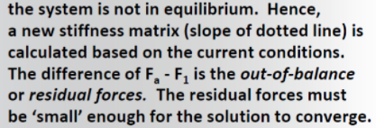 A new stiffness matrix is calculated based on the current conditions (new nodal locations) . A new stiffness matrix does not give the same internal forces as the original stiffness matrix.
In a linear analysis, the internal forces are equal to the external forces. There is no need to update the stiffness matrix. If you apply a 10 N load to a 50 mm thick beam and it deflects 0.0001 mm. I can tell you that if you apply 100 N, it will deflect 0.001 mm and a 1000 N load will deflect 0.01 mm. That is an example of a model where the small displacement assumption is valid and you can use a linear analysis and scale the answer for different loads. That is what NASTRAN does. Inverts the stiffness matrix once, them computes a solution for many load cases from that one inverted stiffness matrix. That is linear analysis.
The PCG solver has a convergence criteria that give similar precision to the direct solver. Read about these two solvers in this section of the help system:
https://ansyshelp.ansys.com/account/secured?returnurl=/Views/Secured/corp/v212/en/ans_bas/Hlp_G_BAS3_4.html?q=PCG%20convergence%20criteria
August 11, 2021 at 4:39 pmRameez_ul_Haq
Subscriberthank you for bearing with me this long I guess I should be spending more time learning and clearing out all the queries. I think there is a ANSYS Innovative course available as well which is dedicated for Newton-Raphson and the idea which we are discussing here. Let me check that out. And also, let me check the link that you have shared.
Thank you again, sir :)
September 6, 2021 at 9:33 amRameez_ul_Haq
Subscriber,hello again on this thread.
This might just be a basic question which you might have already had answered somewhere, but if you could just provide an answer to this thing, I would be glad.
I had two different models whose geometric non-linear analysis I want to conduct. For first of these models, it took 10 substeps to converge (bisection occurred, then substep decreased the time, then again tried to converge, etc). While for the second model, first iteration was conducted at directly 1 sec, then on the second iteration the analysis converged. There was only 1 step i.e. at 1 sec. How is that possible? I mean how can one model require so many substeps and iterations to converge and ultimately reach 1 sec, while the other model can just directly converge at 1 sec with no other substeps, and only two iterations? What makes the difference here?
September 6, 2021 at 12:57 pmpeteroznewman
SubscriberDifferent models will have different stiffness matrices and different loads so each model will have a different amount of initial force imbalance at the end of the first iteration. Some will already satisfy the criterion and others will need to do some iterations or even a bisection.
September 6, 2021 at 1:27 pmRameez_ul_Haq
Subscriber,so the force imbalance depends upon the global stiffness matrix of the model as well as the type and amount of the external force applied, right?
For the first model (which required alot of substeps and iterations), the initial substep value of time was, say, 0.2 sec. But for the second model which immediately converged, the load was applied directly at 1 sec. So how does the solver decide at what time substep should the geometric non-linear analysis begin? I hope you understood what I meant.
September 6, 2021 at 3:08 pmpeteroznewman
SubscriberThere are two programs in use during a nonlinear statics solution, and we loosely call them both "the solver", but it would be more accurate to say there is a "matrix solver" (MS) and a "solution control program" (SCP). The MS is the program called multiple times by the SCP. The MS is what is used exactly once for a linear analysis. The SCP manages the substeps, calculates the Force Imbalance and compares that with the Criterion and decides what to do next: another iteration, increment the load, bisect the load or stop the process with an error or stop with a successful completion.
When you insert a nonlinear item into the model (frictional contact, plasticity, large deflection), that automatically starts the SCP, which calls the MS as many times as it needs.
September 6, 2021 at 4:07 pmRameez_ul_Haq
Subscriber,ohh okay. understood.
what about this one, "so the force imbalance depends upon the global stiffness matrix of the model as well as the type and amount of the external force applied, right?"
September 6, 2021 at 4:18 pmpeteroznewman
SubscriberYes, right.
September 8, 2021 at 12:33 pmRameez_ul_Haq
Subscriber,can you kindly tell me why is this happening. I think the substep should have had already converged when for the first time when the force and moment criterias were met. Unfortunately, the analysis kept on running a few more iterations before the substep convergence has reached. I haven't attached the displacement graph since it is always below the criteria limit.


September 8, 2021 at 1:56 pmpeteroznewman
SubscriberThere are other criteria the solver is checking besides these three before it calls the increment converged. For example, Penetration Tolerance for Frictional Contact or the Pressure Compatibility equation for elements using mixed u-P element formulation. You can see statements on those two written to the Solution Output file to know why the iteration continues.
September 8, 2021 at 7:12 pmRameez_ul_Haq
Subscriber,ohh okay I don't know but I feel like FEA and ANSYS is kinda like a never ending river, where you find a new and different fish everytime you try to walk along with it. I guess calling myself a FEA and ANSYS expert will take way long time than I imagined I thought the convergence criterias were enough but there are some other things as well. I don't know how many more things are still hidden from my eyes hahaSeptember 8, 2021 at 7:19 pmRameez_ul_Haq
Subscriber,I mean if the penetration tolerance is not being met then it automatically means that either some or all of the convergence criterias won't be met, isn't it? Is it possible for the penetration convergence tolerance not being met but other convergence criterias are being met? If yes, then how? Isn't there any relation between the penetration convergence tolerance and the force/moment convergence?
Can you provide a guide from where I can research about the mixed u-P element formulation, please?
September 8, 2021 at 8:53 pmpeteroznewman
SubscriberI have seen the statements in the Solution Output file, something like "there is too much penetration in 17 elements" and I know I can type in the penetration tolerance and make it much smaller because that is important, while the Force Criteria stays at the default value of 0.5% so is is quite possible to have convergence on Force and not on Penetration.
Read this page of the ANSYS Theory Manual to learn about mixed u-P element formulation.
https://ansyshelp.ansys.com/account/secured?returnurl=/Views/Secured/corp/v212/en/ans_thry/thy_geo5.html%23geoupform
Yes, there is much to learn. Aniket posted a link to the history of ANSYS nonlinear development here and I read that. It was most interesting.
November 19, 2021 at 8:13 amRameez_ul_Haq
Subscriber,hello again on this forum sir.
I was thinking that the amount of RAM needed is dependent upon the number of elements (and hence the nodes) within my model because that is the information that the RAM will hold while processors solve the model. Now, regardless of if I use Direct or Iterative solver, the number of nodes within my model still remains the same. So how can RAM requirement drastically decrease if Iterative solver is preferred over the Direct solver?
November 19, 2021 at 10:40 amRameez_ul_Haq
Subscriber,and would Large Deflection ON analysis require more memory than the Large Deflection OFF? If yes, can you please explain why? Because I don't think it should create a difference in the memory requirements for these two, although we know that the former would take more time than the latter. What do you think?
November 19, 2021 at 7:51 pmpeteroznewman
SubscriberThe direct solver uses more memory than the iterative solver because it has to manipulate large data structures to invert the matrix. The iterative solve doesn't invert the matrix, it just guesses at the deformations and keeps iterating on the guess until it gets close enough to stop iterating. It takes less RAM to substitute the deformations into the matrix to calculate the force imbalance than to invert the matrix.
Large Deflection ON determines how many times the matrix has to be solved. Large Deflection OFF is often a single matrix solution. The RAM requirements are the same, but the amount of storage could be different when the solution history is stored and there are multiple converged substeps saved. But that is under user control whether to save the history or not.
November 21, 2021 at 7:04 pmRameez_ul_Haq
Subscriber,okay understood. Thank you for that.
Please have a look at the pictures below.
 So I chose an iterative solver for my analysis, however the solver itself switched to direct (sparse). I actually chose direct solver initially, but the RAM requirements were too much and I had to switch to iterative solver. Unfortunately, this move went to vain since the solver itself again try to use the sparse solver. What is the reason behind this? What can I modify within my model so that I would be able to use the iterative solver only?
And also, will some formulations of the contact will result in fewer equations and hence require lesser RAM than the others?
 I also couldn't understand the warning above. What is the real constant set, and why does it have a number 2281? What is a wave front and how does it affect my solver's performance?
 What does the above warning mean, and why does this happen?
 What does memory resident data base mean?
 Why is there a need to create internal nodes within my model, and why are they created for each of the reasons above?
 In my model, I have a total of around 1 million elements. I go back to the solver output file, and realize that these are the number of elements within my model. Where else does the extra 3 million elements come from? I mean what are its soucres? Will increasing number of joints, contacts or other things affect the total number of elements within my model, or the total number of equations within my model?
 What is the difference between Workspace and Database?
November 22, 2021 at 1:47 pmRameez_ul_Haq
Subscriber,I would be glad sir if you could provide your precious views on these queries :)
November 22, 2021 at 2:41 pmpeteroznewman
SubscriberThe reason is given in the WARNING
 What can you do to avoid switching from Iterative to Sparse solver? Don't use u-P formulation. Don't use MPC184 elements using Lagrangian multiplier. Don't use constraint equations.
 Every contact pair is given a number before it is sent to the solver. These numbers are called real constants. The numbering is arbitrary. When a stiffness matrix is assembled, the dimensions are large. If the number of DOF in the model is N, then there are NxN entries in the stiffness matrix, but most of them are zero, which is why it is called a sparse matrix. There are special direct methods to invert a spare matrix. If you had a cantilever beam and meshed it with 100 beam elements, that would be a 600x600 stiffness matrix because each node has 6 DOF. The nonzero entries in the stiffness matrix are organized to be as close to the diagonal as possible. The width of the nonzero entries is called the wavefront. In the case of a beam element, where each node only touches 2 elements, that has the smallest wavefront. The larger the wavefront, the more memory is required while inverting the matrix. When you add a Remote Displacement and scope it to many nodes, that increases the wavefront.
 This warning says that the element connects one node to node 0, which is a grounded node. If this is not what you wanted, then you could take action to change the model to make it the way you intended. Having unintentional connections to ground can ruin a model's results since a ground connection adds a boundary condition that can greatly affect the result.
The memory resident database can be ignored. It is a small amount of memory that is automatically managed by the solver, so pay it no further attention.
 Remote points are internal nodes, which are also called pilot nodes. They are needed to apply remote forces or remote displacements.
 You have about 4 million elements total, but you and 2 million nodes. If the nodes are on solid elements, each node has 3 DOF so there would be about 2x3 = 6 million DOF in the model.
Look for a table like this in your model:
 That is where it tells you how many contact elements were added to the solid elements that you created.
What is the difference between Workspace and Database? ANSYS automatically manages memory so you don't need to interfere with it. If you run out of RAM, reduce the model size or install more RAM. Trying to override the ANSYS settings can, in rare circumstances, get a model to run without doing either of those things, but more frequently leads to failure.
November 22, 2021 at 4:25 pmRameez_ul_Haq
Subscriber,so what appears to be the reason for almost 3 times more number of elements which appear within my model? Only contacts, or something else like joints, remote forces, etc? Or this is something which always happen whether I have these things (contacts, joints, remote forces) within my model or not.
November 22, 2021 at 4:34 pmpeteroznewman
SubscriberThe reason will be revealed when you show the number of contact elements added to your model which is listed in the Solution Output as in the example I showed above.
If you have a thin slab of material meshed with a single layer of SOLSH190 elements making frictional contact to a rigid surface and pressed down by a rigid surface, you could end up with 5 times the number of elements in the solution as solid elements in the mesh: Target and Contact for the bottom face, Target and Contact for the top face. That is 4 times + 1 count of SOLSH190 elements.
November 22, 2021 at 9:41 pmRameez_ul_Haq
Subscriber,"What can you do to avoid switching from Iterative to Sparse solver? Don't use u-P formulation. Don't use MPC184 elements using Lagrangian multiplier. Don't use constraint equations.", How can I avoid using u-P formulation elements? and I mean the warning says that the MPC184 elements using lagrange multiplier entangle with other constraint equations. I guess I have to keep the topologies to which I am applying MPC184 elements free from any other constraint equations, in order to make the PCG solver to work.
"This warning says that the element connects one node to node 0, which is a grounded node.", why does the solver do that without me specifically giving that as a command to the solver? To avoid rigid body motion, or it has other intentions?
Can you atleast tell me what does Workspace and Database mean briefly? I would keep this information in mind for the future. Thank you.
November 22, 2021 at 10:30 pmpeteroznewman
SubscriberIt's easy to avoid using u-P formulation in Mechanical because you have to use a Command Object under a body and set Keyopt(6)=1. However, if you use a hyperelastic material model, the solver might automatically set Keyopt(6) for you. You can stop it from doing that by setting Element Control to Manual.
 I have never noticed a warning like the one above. You can chase it down by finding that element and see what kind of element it is.
Read this discussion to learn about Workspace and Database: /forum/discussion/7287/increased-ram-but-still-says-insufficient-memory/p1
November 23, 2021 at 11:22 amRameez_ul_Haq
Subscriberthank you for your reply. But doesn't setting Keyopt(6)=1 actually implements the mixed u-P element formulation, instead of avoiding it? So the easiest way to avoid using the mixed u-P element formulation (instead of adding anything under the body inside the command object) would be to directly switch the Element Control to Manual, regardless of if the material is hyperelastic or not, right? I can do that but I want to know what would be the pitfalls or cons of doing so.
Regarding the number of contact and target elements within my model, they begin and end like this:
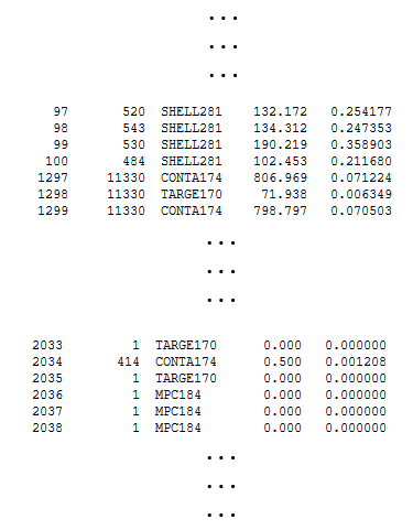 Just one more thing; how can I avoid using MPC184 elements using lagrange multipliers? I saw a this inside ANSYS help.
 So I think that MPC184 elements are supported by the PCG solver. I don't understand the phrase, "it entangles with other constraint equations". I mean does it mean that the topologies where I am applying the MPC184 elements (which uses lagrange multipliers) also are scoped to some other constraints, like supports, joints, etc?
In order to avoid this problem, one option is to completely avoid using MPC184 elements using langrange multipliers. How can I do this, can you please help me out?
November 23, 2021 at 12:30 pmpeteroznewman
SubscriberYes, you have correctly interpreted my first sentence. I could have added a clarifying phrase at the end, "so don't do that", but you got my point. The downside to avoiding mixed u-P element formulations is in models with highly incompressible materials where Poison's ratio is almost 0.5 or where hyperelastic materials are being used. Some of these models will not converge without the mixed u-P element formulation.
Looking at the table of elements, it answers your question of why you have 1 million solid or shell elements and an additional 3 million other elements. Oh, and in my example with SOLSH190 above, where I got to 5x more elements, I could get to 9x more elements if each of the contacts were set to symmetric where ANSYS duplicates the contact but reverses the sides for Target and Contact.
I don't fully understand the "entangles" phrase, but it could mean the case where you have one set of contact elements or a joint on one face and another set of contact elements or a joint on another face and they share a set of nodes on the common edge. You often see warnings about that.
This part of the ANSYS Help system tells you how to avoid using Largrange Multipliers in MPC184 elements.
https://ansyshelp.ansys.com/account/secured?returnurl=/Views/Secured/corp/v212/en/ans_elem/Hlp_E_MPC184.html
November 23, 2021 at 1:38 pmRameez_ul_Haq
Subscriber,okay I will read the link you shared in order to avoid using MPC184 elements which use lagrange multipliers. I just want to erase all the ways which may lead to mandatory use of Sparse (Direct) solver within my model, because I don't have enough RAM to do that. Not using Lagrange Multipliers in MPC184 elements has its own drawbacks as well, sir? What would you say?
I decreased the total number of elements within my model, so now they are 548,769 elements (which includes only solid, shell and beam) and a total of 1,129,629 nodes within my model. For this, I got something inside solver output as shown below.
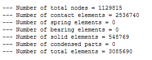 I mean yes, for the 'Numer of total nodes', I can understand that why they are a little bit higher than those within my model (because some extra pilot nodes maybe created during solution). But for the 'Number of solid elements', they are equal to those within my model but my model has these elements which are not just solid; it also inlcudes shell and beams. So I don't know why does the solver classify all of these under the name, "solid elements'' within solver output file.
Anyways, the above picture can easily tell me the total number of contact elements which are created within my model, and why are these the reason that I see dramatic difference between the 'Number of total elements' in solver output file and those within my actual model. Would you suggest something to decrease these total number of contact elements, because these are the reason why RAM requirement drastically soars.
Plus, what does Total CP and Average CP means?
November 23, 2021 at 3:36 pmpeteroznewman
SubscriberI don't know exactly what CP stands for but it is some measure of the Computer Processing that occurred to do some task such as writing the stiffness matrix.
You have to do extra work to avoid using Lagrange Multipliers in MPC184 elements in your model. For example, if you have a Revolute Joint in the model, the default element constraint imposition method is Largrange multiplier method, but if you use Keyopt(2)=1 under the joint, you can switch it to use a Penalty-based method.
In the summary you show, shell and solid elements are grouped into the solid element bucket. Elsewhere in the solution output, it counts out the actual number of shell and solid elements.
Why does the model have so many contact elements?
In a large system, there may be 10 different regions-of-concern (ROC). It seems you have done mesh refinement and added frictional contact in all 10 areas to try to get accurate stress results in all 10 areas in one model, but that has resulted in a model that does not run in available RAM. Some companies have computers with 256 GB or 512 GB of RAM and can run such a large model, but these models will take tens of hours of solution time to solve.
One way around the issue of running out of RAM is to make 10 versions of the large system. Each version has the mesh refinement and frictional contact in only one ROC and all the other ROCs are idealized to a coarse mesh and bonded contact (or shared topology). The stress results are only reported in the one ROC that is refined in that model. Yes, it it 10 times more work to make 10 models, but at least you get results using the RAM you have and each of the 10 models solves in much less time than the global model with refinement in all 10 ROCs at once.
November 23, 2021 at 4:26 pmRameez_ul_Haq
Subscriber,should I be cautious while switching the MPC184 elements to penalty-based method? I mean will it affect my solver performance, results, etc?
Can you write down the exact command (in APDL format) that should be given under that joint, to switch it to penalty based method, here please?
Firstly, I would like to clarify that my model does not have any kind of non-linear contact. It has just linear contact, infact just bonded contacts. But will the non-linear contacts result in more RAM requirement than the linear contact? (assuming that the non-linear and linear both contacts have the same Contact and Target faces). And also, I haven't added any mesh refinement near these contacts. The global mesh size is the same as the local mesh size near these contacts.
Secondly, I would like to know if the increase in contact elements actually affect the memory requirement for the model to run? Because as I know, its not the elements but the nodes of all the elements within the model which plays a role in determining the amount of RAM needed for the analysis to run (since its the nodal properties that would be held by the RAM while processor does its thing). Now as far as the contact elements are concerned, does it also contribute to the overall increase in nodes in my model, and will these nodes be treated as like typical model nodes (whose displacements are calculated by the solver)? If it will, then yes it makes sense that the increase in total contact elements would ultimately require more RAM, but if it doesn't then it doesn't justify the increase in total required RAM.
Will changing the Formulation of the contact (regardless of linear or non-linear contact), detection method or behavior result in lesser number of contact elements, and hence lesser RAM requirement?
November 23, 2021 at 7:25 pmpeteroznewman
SubscriberIf you are using Bonded Contact, it will not make much difference which formulation you choose. The big impact is where some formulations allow the Iterative Solver while other prevent the use of Iterative and automatically switch to the Direct Sparse solver. If you have a very large model that won't solve with the Direct Sparse solver due to a lack of RAM, then choosing a formulation that allows the Iterative solver to run is the difference between having a result and having no result.
Here is the command to put under under a Joint: keyopt,_jid,2,1 The disappointment is that the solver still detected an MPC element and automatically switches to the Direct Sparse solver.
Here is an example bonded contact that has the formulation of MPC. The analysis settings are set to Iterative solver and it runs using the Iterative Solver.
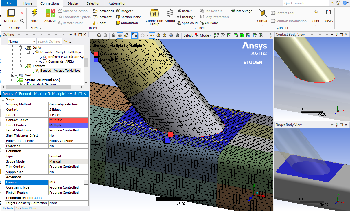
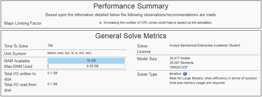 If I suppress the Bonded Contact and use a Revolute Joint, the solver automatically switches to Direct Sparse, even though I have a Command Object to set the Penalty method.
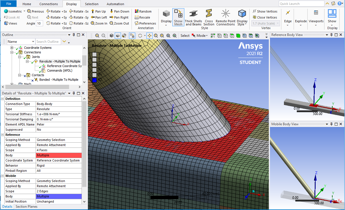
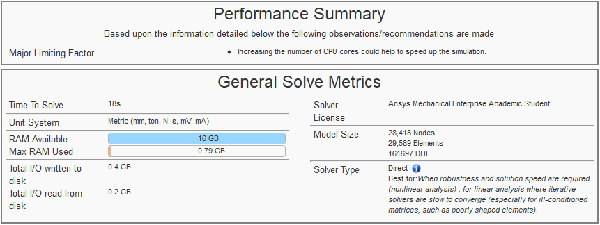
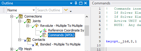 Maybe someone from Ansys can explain why this keyopt, which is supposed to switch the method on the joint from Lagrange to Penalty, doesn't prevent the auto-switch to the Direct solver.
If you have only Bonded Contact and no Joints, you might be able to get the model to run using the Iterative solver.
Contact elements increase the size of the model and the RAM requirement compared with using no contact elements and either using Mesh Merge in Mechanical or Share button in SpaceClaim.
Contact elements hurt the RAM requirements because they connect nodes that are far away from each other in the network of elements in the model (even through the nodes are close spatially) and increase the wavefront during the solution process. When you do node merge or Shared Topology, the wavefront may be smaller than when contact elements are used.
How much RAM is in your computer? How much RAM does the motherboard support? Have you requested additional RAM to max out the RAM in your computer? If not, you should.
November 23, 2021 at 8:07 pmRameez_ul_Haq
Subscriber,so what I understood from your reply is that either I use linear or non-linear contacts, the total number of contact elements built by solver are still going to be somewhat the same (for the same contact and target faces). I cannot do much to modify (infact decrease) these number of contact elements, unless I decrease the size of the mesh by my own on the bodies between which I applied contact. Moreover, the formulation and detection method still won't provide that much of a help in decreasing the number of contact elements built by solver.
Plus, I also got to know that symmetric will indeed kinda double the total number of contact elements within my model, hence requiring more RAM. So what is the default program controlled option for contact behavior?
Now, as you just informed me, we know that MPC formulation will allow me to use Iterative solver. What other contact formulations will allow and prevent me to use the Iterative solver?
So yes, that is something which I was also experiencing. Even though by adding that APDL command under all my joints (fixed, revolute, cylinderical, spherical, etc) to switch to Penalty Method and avoid using the Largrange Multiplier, it was still not giving up using the Sparse solver. I thought I was doing a mistake in writing the command but apparently its also not working for you. So it means that even if we are using the the contact formulation which allows the use of Iterative solver, we won't still be able to use the Iterative solver if the model also involves joints Yes, I hope too that if any ANSYS Employee could address this issue on how can we actually switch any joints' formulation of MPC184 elements from Largange Multiplier to Penalty Based so that we could be able to implement Iterative (PCG) solver only.
November 23, 2021 at 9:49 pmpeteroznewman
SubscriberBonded contact doesn't have a behavior that doubles up contact elements. For Frictional contact, the Program Controlled behavior is Auto-Asymmetric, so you have to choose Symmetric to double up the contact elements.
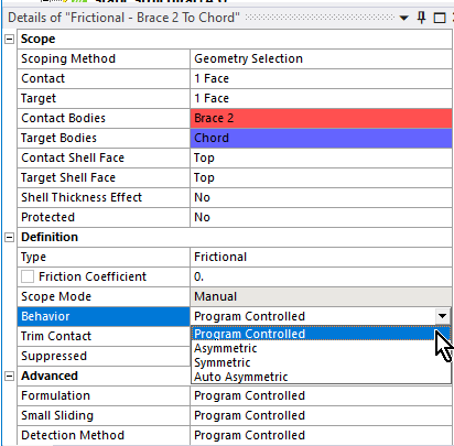 The Augmented Lagrange Bonded Contact Formulation, which is the Program Controlled default, allows the Iterative solver to be used. The Pure Penalty and Beam formulations allow the Iterative solver to be used.
Only the Normal Lagrange Formulation of Bonded Contact forced the Direct solver to be used.
November 24, 2021 at 10:40 amRameez_ul_Haq
Subscriber,please observe the picture below.
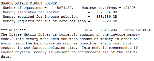 I was actually not using the distributed solver, however the solver by itself switched to the in-core memory mode. Distributed actually means in-core and unchecking the distributed will make the analysis run in out-of-core memory mode, right? However, even after unticking the distributed option, the solver still ran in in-core memory mode. Can you guess any probable causes behind this?
November 24, 2021 at 1:14 pmpeteroznewman
SubscriberDistributed does not mean in-core. Those are two different things.
In-core vs. Out-of-core
In-core means the solver can hold all the data in RAM while it inverts the matrix. Out-of-core means the solver writes a lot of data to storage (HDD or SSD) while it manipulates some of the data in RAM during the solve process, then writes that portion to storage and reads a different block from storage to manipulate in RAM to continue the solve process. This obviously makes the solution take longer since the access time to a block of data in storage is orders of magnitude slower than the access time to a block of data in RAM. That is why it is vital to have as much RAM as the computer (or the budget) can support.
Large models will not solve in-core, so it is vital to have the fastest storage available, which is SSD. If the computer only has HDD storage, installing a SSD is a nice upgrade for large model solving.
ANSYS will always try to run in-core if it estimates there is enough free RAM to do so. A command object can force the solver to run out-of-core if you have some special reason to not let ANSYS use all available RAM, such as when the solution takes tens of hours to run and other tasks need to run on that computer later in the day and you want to reserve some RAM for later use. I have never used that command.
Distributed Memory vs. Shared Memory
Distributed Memory is used when you tick the box Distributed. This setting almost always solves in less time than when you leave the box unticked, which means the solver uses the Shared Memory parallelism. ANSYS Help has an easy to read section explaining these two types of Parallel Processing.
https://ansyshelp.ansys.com/account/secured?returnurl=/Views/Secured/corp/v212/en/ans_dan/dan_overview1.html
One reason to untick Distributed is to try to get a large model to run in-core after learning that when Distributed was ticked the model ran out-of-core. Large models often solve in less time using the Iterative PCG solver or won't run at all with the Direct Sparse solver. The PCG solver uses less memory to run in Shared Memory than in Distributed Memory so the largest models may require unticking the Distributed box. ANSYS Help has a section explaining how different solvers (Direct vs Iterative) and different memory choices (Distributed vs Shared) affect the amount of memory needed.
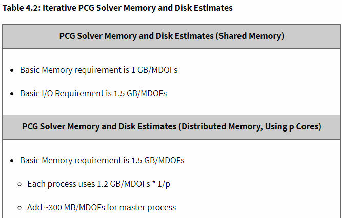 https://ansyshelp.ansys.com/account/secured?returnurl=/Views/Secured/corp/v212/en/ans_per/per_intro.html
November 29, 2021 at 4:56 pmRameez_ul_Haq
Subscriberthank you for a detailed elaboration on these.
Can you just give inform me if I a very huge target face but the contact face is still small, and on the other hand I have splitted the target face (in DesignModuler or Spaceclaim) to be nearly the same as contact face, then should the number of contact elements be higher in the former case or they should still be the same for both cases?
November 29, 2021 at 6:44 pmpeteroznewman
SubscriberSure, there will be fewer TARGET elements when you create a smaller face, but the solve time will be almost the same because it is the CONTACT elements that do all the work and consume CPU cycles and that didn't change.
December 2, 2021 at 7:27 amRameez_ul_Haq
Subscriber,what about the joints? I mean yes if I decrease the number of elements then overall RAM requirement and also the time required for the analysis to complete will be reduced. But will increasing the number of joints within my analysis also have an impact on the RAM requirement and time to solve, or not? I mean like will it be similar to what we expect with the contact elements, or no?
December 2, 2021 at 12:53 pmpeteroznewman
SubscriberDo you mean Fixed Joints? Of course if you have no fixed joints and add hundreds of them to your model, there will be a small impact on the required RAM and solve time.
Fixed Joints should not be used to connect large areas together. Bonded contact is more appropriate for large areas. Replacing Bonded Contact with Shared Topology can reduce RAM requirements if it can be done without increasing the number of nodes.
December 2, 2021 at 5:09 pmRameez_ul_Haq
Subscriber,yes you got what I was trying to do, i.e. to replace the bonded contacts with the fixed joints since I am not still not satisfied with the shared topology (so lets just leave away the shared topology for now).
Why would fixed joints be less and bonded more appropriate for larger areas?
And how would a fixed joint work? I know it applies contraint equations to each and every node of thes scoped topologies, but will it generate any additional elements within my model (like a bonded contact does) and can it have an impact on the RAM similar to what bonded contacts have (assuming both are being used for the same topologies)?
December 2, 2021 at 7:45 pmpeteroznewman
SubscriberSay you have a 1m x 1m square surface meshed with 10 elements (11 nodes) on the side, there are 121 nodes on that surface. A second coincident surface has the same size mesh. If you use Bonded Contact to connect the adjacent surface using MPC formulation, there will be 121 constraint equations spread across the area holding each individual pair of coincident nodes fixed in 3 DOF. Bonded Contact will allow the 1m x 1m surface to deform within that area, while keeping each pair of nodes together. This is good and will give you the same result as shared topology.
If you connect those two surfaces with a Fixed Joint, there will be one new node at the center of each surface and a single constraint equation holding those two new center nodes fixed in 6 DOF. Then there will be two constraint equations, one from each of those new nodes at the center that spiders out to the 121 nodes on each surface. Now you have to choose whether the Joint has Rigid behavior or Deformable behavior. Rigid is no good because now you added a rigid face to the structure that wasn't there before. Deformable is no good because the nodes closest to the center have higher influence (weighting factor) on the new node than the nodes furthest from the center. This is very different to Bonded Contact.
December 3, 2021 at 9:35 amRameez_ul_Haq
Subscriber,please observe the picture below.
 So the analysis was solving without any Rigid Body errors but I was getting this in my solver output file. Since pivots are essentially associated with Rigid Body errors, so I was confused that why it wasn't causing a Rigid Body Motion. Plus, what would be the difference between maximum pivot and minimum pivot?
December 3, 2021 at 8:57 pmpeteroznewman
SubscriberThe following paragraph was written by in this post: /forum/discussion/1730/solver-pivot-warning
Some general explanations on what "pivot error" means in FEM.
The pivot or pivot element is the element of a matrix, or an array, which is selected first by an algorithm (e.g. Gaussian elimination, simplex algorithm, etc.), to do certain calculations. In the case of matrix algorithms, a pivot entry is usually required to be at least distinct from zero, and often distant from it. (source:https://en.wikipedia.org/wiki/Pivot_element). A negative or zero equation solver pivot value usually indicates the existence of a singular matrix with which an indeterminate or non-unique solution is possible. In ANSYS when a negative or zero pivot value is encountered, the analysis may stop with an error message or may continue with a warning message, depending on the various criteria pertaining to the type of analysis being solved. You may also read ANSYS Help > Mechanical APDL > Basic Analysis Guide > Solution > Singular Matrices to access more details.
So Rameez, in your screen grab, the minimum pivot is positive and far from zero, so no rigid body error is issued and the matrix can be inverted.
The maximum pivot is just what is says it is.
NASTRAN has a check on the maximum pivot ratio and will generate a FATAL error if the value exceeds 1e7.
https://www.mscsoftware.com/support/files/SimAcademy/wm147/Excessive_Pivot_Ratios%20Cheatsheet_2011_11_10.pdf
I don't know if the NASTRAN check is the same as the maximum pivot/minimum pivot numbers you show in your screen snap. Excessive pivot ratios hurt solution accuracy, so ANSYS probably has some warning on this condition but I don't know what that looks like.
December 5, 2021 at 2:06 pmRameez_ul_Haq
Subscriberthankyou for your replies, this one as well as the one before this.
Deformable is no good because the nodes closest to the center have higher influence (weighting factor) on the new node than the nodes furthest from the center
What kind of problem can this bring in? Did you mean that the nodes closer to the center might have higher share of force transfer and thus might have higher deformations then the rest of the nodes, which are far away from the center?
So as far as I can comprehend, the bonded contact and fixed joint won't make that much of a difference in accuracy if the locally connected topologies are small. However, if the locally connected topologies become large, then fixed joint will not closely mimic the reality and will loose the accuracy as compare to the bonded contact.
How would you rate the convergence between fixed joint and bonded contact? I mean can it cause some convergence problems for any of these two? If yes, then which would be more prone to it?
December 5, 2021 at 3:05 pmpeteroznewman
SubscriberYes, for a small area, there is little difference in nodal deformations between a fixed joint and bonded contact. The advantage of a fixed joint is how easy it is to extract the force transfer through that area.
For two large areas connected by a deformable fixed joint, the coincident nodes far from the center may gap or penetrate, which would not happen if it was bonded contact.
There is not much difference in convergence between bonded contact and a fixed joint, but I think a fixed joint is more likely to have issues.
December 5, 2021 at 3:09 pmRameez_ul_Haq
Subscriber,and what would you say about this one?
"the nodes closer to the center might have higher share of force transfer and thus might have higher deformations then the rest of the nodes, which are far away from the center?"
December 5, 2021 at 3:12 pmpeteroznewman
SubscriberYes that could happen for a large surface connected by a fixed deformable joint, but it is load specific.
If it was a pure tension/compression, then that might happen.
But if it was a moment, then the largest deformation might be at the nodes furthest from the center.
December 5, 2021 at 5:20 pmRameez_ul_Haq
Subscriber,okay yes, true. Makes sense. So basically the fixed joint (deformable) is scoping the whole face (target or mobile) to a single point (i.e. remote point) and the force on that point is then transferred to the rest of the nodes that this remote point is scoped to. So it is working kinda like a remote force. Whereas for bonded contact, there is relative transfer of forces from local nodes on contact face to local nodes on target face. And yes, no penetration in bonded contact but can exist during solution in the fixed joint. Understood.
I would just like to ask one more thing here in regards with bonded contact. If I have two faces and I want to develop bonded contact between them, so the general thumb of rule is that the smaller face should be given contact while the larger face should be given contact. So I am guessing that this is because (as you have already mentioned in this thread) that its the contact elements which influence the solution time, so we want the smaller face to have contact so that it could result in smaller number of contact elements, while if the larger face is given the contact then it could result in larger number of contact elements which could affect the solution time adversely. Is that true?
Plus, what would be the benefit of using asymmetric contact as compare to symmetric? All I see are benefits and no pitfalls, like smaller number of contact elements plus an a single face where contact pressure could be assessed after solution. The only difference I see is that the symmetric doesn't allow both, the target face cannot penetrate the contact face and contact face can also not penetrate the target face, while the asymmetric only allows the contact face to not penetrate the target face. How can that affect my results at all? Furthermore, doesn't contact face not penetrating the target faces automatically implies that target also cannot penetrate through the contact face?
December 5, 2021 at 6:09 pmpeteroznewman
SubscriberYour first and second paragraphs are correct and true.
Symmetric contact is very rarely needed and is harmful when it is used when it is not needed. It is harmful because it splits the pressure between two faces, making it difficult to measure pressure. It is harmful because it slows down the solution by doubling up the contact elements. I have never needed to use symmetric contact.
January 15, 2022 at 9:50 pmRameez_ul_Haq
Subscriber,for this warning:
 How can i know which contact is changing the status to no-contact, if I have got many non-linear contacts within my analysis? I mean the only element I can search are the mesh elements, but searching the contact element which is abruptly changing its status, I don't know how to do it.
January 16, 2022 at 12:01 ampeteroznewman
SubscriberI don't know how to see where that element is either, but I've never needed to know. These warning are produced often because contacts open and close during a nonlinear analysis. As long as the solution converges to the full load, and the deformed shape and contact pressure look good, you can ignore the warning.
January 16, 2022 at 12:33 amRameez_ul_Haq
Subscriberthe problem is I am seeing a similar warning within my analysis at the first substep. After this warning, the solution suddenly stops, notifying me that there might be a rigid body motion due to insufficient supports. Now the problem is, I know I have supplied sufficient supports to my model to not cause any RBM, but I have many non-linear contacts as well and I am thinking one of these contacts are creating a problem. So I wanted to know how can I navigate to this contact, specifically.
January 16, 2022 at 11:10 ampeteroznewman
SubscriberIt may be possible to open the model in the Mechanical APDL classic UI to visualize that element. Maybe an expert in APDL will reply with that information.
Maybe the sudden contact change is the reason for the solution stopping, maybe not. What was the error at the end of the solution output file?
Diagnostic troubleshooting methods are what I use to isolate the cause of the error. Change the frictional contact to bonded contact. Add fixed supports. Suppress parts of the model. By using a careful search strategy such as bisection, you can rapidly isolate the source of the error.
January 16, 2022 at 12:36 pmRameez_ul_Haq
Subscriber,I swapped just one the frictional contact with bonded, and yes it worked fine. I just picked that frictional contact which i felt was the cause of problem, and it solved the problem for RBM. But in reality, that contact is no bonded but is actually frictional. So to model the structure appropriately, should I be going for transient instead? What whould you say?
January 16, 2022 at 4:18 pmpeteroznewman
SubscriberIf you expect there to be a static solution, then you want to see why the original contact failed to support the load. Change that contact to Rough, which means it has an infinite coefficient of friction, but it can separate. Will it solve? If it does, then the friction you specified is too low to provide a static solution, but a larger coefficient of friction would solve.
If Rough does not solve, then the load is causing the contact to open. Change it to a No Separation contact and see if it solves. Try to figure out why the load is pulling that contact apart.
January 21, 2022 at 9:18 pmRameez_ul_Haq
Subscriber,makes sense. Thanks. But the problem is sir I know I have made the contacts absolutely correct, and just trying to diagnose the problem within a contact and then applying changes to it so that it can behave static, then the structure would solve but it still would not mimic what would happen in the reality in an accurate manner.
I mean sir usually what happens is that the designer sends a structure, asking the analyst to assess the strength of that structure. Now, he doesn't know if the structure is going to behave static or not, since he is not aware of the loads. The loads are determined by us, essentially. However, we are not sure either if these loads will cause the structure to behave statically or not. So I don't know how to decide on that. If I directly go for static analysis, then inputting so much effort on the pre-processing might go in vain if I realize that the structure is performing a Rigid Body motion. I would be glad if you can give me suggestions or tricks on how to figure out initially (without doing any FEA) if we should even go for a static analysis for this certain structure (under some specified loading conditions) or not.
I can go for a modal analysis first, because you have suggested that to me in some other posts in the past. However, the problem with modal analysis is that it doesn't include contact non-linearities. So I don't think it is useful at all for these kinda situations.
January 21, 2022 at 10:21 pmpeteroznewman
SubscriberMy previous reply was describing how to diagnose the problem with the design. As you say, there is nothing wrong with the contact.
A design is either intended to be a mechanism or not. While the parts of a mechanism can have rigid body motion, they can also be analyzed in Static Structural by proper selection of supports. That starts with a Free Body Diagram and supporting all six degrees of freedom.
FE models of a structure might have mistakes in them that lead to the model having a zero pivot error due to the presence of an un-intended mechanism. Modal analysis can help diagnose the mistake in the Static Structural model.
January 22, 2022 at 8:36 amRameez_ul_Haq
SubscriberFE models of a structure might have mistakes in them that lead to the model having a zero pivot error due to the presence of an un-intended mechanism. Modal analysis can help diagnose the mistake in the Static Structural model.
Can you kindly suggest how can this be done? What kind of mistakes were you talking about here? I mean mistakes of loose supports or connections? Because the way I see it, I need to convert the non-linear contacts to linear first to run a modal analysis. So basically, I am making enormous assumptions there. I mean when transforming the non-linear contacts to linear in Modal, I might see everything is fine in Modal but still resulting in some RBM errors in Static Solver.
Furthermore, assume there are no non-linear contacts in the static analysis, but still I see some RBM errors. I go to modal, and conduct the analysis and see first 3 modes having a natural freq of 0. Now, how can I know in which directions my model is lacking translational and/or rotational stiffnesses?
January 22, 2022 at 12:47 pmpeteroznewman
SubscriberThere are many ways to make a mistake that leads to a zero pivot error, for example, in a Remote Displacement, typing a 0 in the wrong DOF and leaving the required DOF as Free, or in a General Joint, turning on the wrong constraint and leaving a required constraint out. Forgetting to use Shared Topology to connect two parts of a mesh. Forgetting to add a bonded contact.
You don't need to manually convert nonlinear contacts to linear before you run a modal analysis. Mechanical automatically changes closed frictional contacts to bonded contacts.
If you get a RBM error in Static Structural and run a Modal on that, you will see several (often six) zero frequency modes in the results table. Plot displacements for all modes solved, the color of the part that is moving is red and the rest of the structure is blue. If the part that is moving is hidden inside, look at the Details window where a line lists the component in the assembly that has the maximum displacement.
January 22, 2022 at 1:07 pmRameez_ul_Haq
Subscriber,okay so I find out the part within my structure which is undergoing RBM. I am guessing if, for example, I see only first 3 modes at zero freq in modal analysis, then that part is lacking stiffness in only 3 DOFs. Am I correct? How can I know these 3 DOFs, where I have to add stiffness within the static solver, to cause it to solve?
January 22, 2022 at 2:46 pmpeteroznewman
SubscriberOnce you can see the part that has the maximum deformation in the first three zero frequency modes, play the animation and see what direction it moves. Do that for each mode that you made Displacement plots for. Add some kind of connection to provide stiffness to ground (through other parts or directly) in those directions then rerun the Modal analysis.
February 14, 2022 at 12:00 pmRameez_ul_Haq
Subscriber,you mentioned here that You don't need to manually convert nonlinear contacts to linear before you run a modal analysis. Mechanical automatically changes closed frictional contacts to bonded contacts.
So all the non-linear contacts are automatically switched to bonded, or some are switched to no separation as well?
Does the non-linear contact needs to be 'closed' initially to be changed to linear contact in modal, or near-open contact will also be automatically switched to linear contact?
February 14, 2022 at 5:23 pmpeteroznewman
SubscriberIn a Modal analysis, Frictional and Rough Contacts are automatically switched to Bonded only if they are Closed. If they are Open, they don't exist in the Modal analysis.
Frictionless Contacts that are closed are automatically switched to No Separation contacts if they are Closed and don't exist if they are Open.
Near open and Far open are both Open.
April 1, 2022 at 3:30 pmRameez_ul_Haq
Subscriber,hello and welcome back to this thread.
We have had a discussion (in page 3 of this thread) about the bonded contact (formulation = MPC) and fixed joints, but still I am not able to comprehend completely that which one of these methods would results in more time taken for the analysis, for the same scoped topologies? Consider the example below.
First, lets just talk about bonded contact (formulation = MPC).
 So for a pinball radius of 1.025 mm, I see only 4 spiderlegs spearding out from a single node, however for a pinball radius of 2.5 mm, I see 8. As far as I can understand, spiderlegs basically means that the 3 DOFs for that node (from where they are spreading out) should be equal to each of the other nodes (of the other face) to which they are extending. Each face (between which the bonded contact is constructed) has 25 nodes, so esentially 25 constraint equations must be developed within the model during analysis by the solver. Now the problem is, if I change the pinball radius from 1.025 mm to 2.5 mm, each node now must have 3 DOFs equal to the each of the other 8 nodes (to which the spiderlegs are extending) on the other face, although the total number of constraint equations are still the same i.e. 25 since the number of nodes are the same. So what do you think, should the value of pinball radius have an impact on the total time required for solution for this case, or not? Each constraint equation within the MPC formulation of bonded contact now would have more variables involved (since the spiderlegs have jumped from 4 to 8), but the number of constraint equations are still the same.
Secondly, what if a surface body - surface body bonded connection (formulation = MPC) was constructed? Now each node on one surface body (whose spiderlegs are extending to nodes on the other surface body) should have 3 DOFs being equal requirement, or now it should have 6 DOFs being equal requirement?
Thirdly, are these spiderlegs of rigid behavior or deformable behavior in these bonded contacts (formulation = MPC)?
Now, lets talk about the fixed joint (behavior = deformable) case.
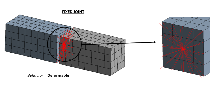 You mentioned this previously on this thread
If you connect those two surfaces with a Fixed Joint, there will be one new node at the center of each surface and a single constraint equation holding those two new center nodes fixed in 6 DOF. Then there will be two constraint equations, one from each of those new nodes at the center that spiders out to the 121 nodes on each surface.
So how many constraint equations in total exist here? Only 1, or 3? I think 3 constraint equations exist because one constraint equation connects all the nodes on the left face to an additional new center node, second constraint equation does the same but with right face, and the third constraint equation connects these two additional center nodes with each other, in all 6 DOFs.
Since the bonded contact (formulation = MPC) just concerns 3 DOFs for the above example, hence a total of 75 constraint equations must be constructed, while since fixed joint concerns all 6 DOFs, so I think 18 constraint equations must be constructed. But the variables involved in the constraint equations of fixed joints are more, since all 25 nodes are connected to a single center node, while for the bonded contact, its either 4 (for pinball radius of 1.025 mm) or 8 (for pinball radius of2.5 mm). So in the light these scenerios, which will take more time to solve, BONDED or FIXED JOINT?
April 2, 2022 at 11:12 amRameez_ul_Haq
Subscriber,would be glad to learn your views on this one, sir :)
April 2, 2022 at 11:26 ampeteroznewman
SubscriberIf you want to know which type of connection takes less time, solve two models and look at the Elapsed Time in the Solution Output file. The difference in solution time should not drive decisions on what connection technology to use and is likely to be an insignificant factor in the elapsed time anyway.
The best practice for bonded contact is to have no gap and a small pinball radius so as to get a node-to-node spider as I show in your other discussion: /forum/discussion/comment/153061#Comment_153061
One place to intentionally use a large pinball radius is when a beam connection is made between two surfaces with holes in them. A pinball radius equal to half the diameter of the washer can be used to control the diameter of the surface the spider reaches without having to imprint the washer diameter into the surface in geometry.
April 2, 2022 at 12:31 pmRameez_ul_Haq
Subscriberthankyou for answering.
I just wanted to understand the impact and effect of increasing the pinball radius on the time elapsed during the solution, and the reason behind it. And also the differences in the time taken by the solver for fixed joint and bonded (MPC) contact, and the reasons behind it. I can check the time taken from the Solution Output file, but I wanted to have a grip over the reasoning that why is it happening. Thats why I commented here to know your views that because of what reasons should increasing/decreasing the pinball radius impact time elapsed, and because of what reasons should switching from fixed joint to bonded contact (or vice versa) impact the time elapsed.
Viewing 74 reply threads- The topic ‘Does non-linear analysis in ANSYS also make use of direct solvers or not?’ is closed to new replies.
Innovation SpaceTrending discussionsTop Contributors-
4924
-
1613
-
1386
-
1242
-
1021
Top Rated Tags© 2026 Copyright ANSYS, Inc. All rights reserved.
Ansys does not support the usage of unauthorized Ansys software. Please visit www.ansys.com to obtain an official distribution.
-


