-
-
January 26, 2025 at 7:50 am
Dennis Chen
SubscriberDoes interface elements or contact based debonding exist for shell elements inside Ansys Mechanical?
Based on my experience and some studying I've done on this topic, INTER203, INTER204, INTER205 are what's created for plane183, solid 186/187 and solid185/solsh190 elements. There doesn't seem to be an interface element for shell elements that I can find.
In terms of contact based debonding, I simply cannot create it and I also don't see a clear indication in the documentation that this can be done.
I want to make this post to see if anyone can tell me that I am wrong because I don't know what I don't know and I need to verify this. Also, shell elements are so critical in so many large scale models becuase a lot of things in reality are made from parts that are tubes/sheets, etc that can and definitely needed to be mid-surfaced. Not having this capabilities is a major issue if this is indeed the case in my opinion which is also why I hope to double check this.
Thank you very much in advance for your help!
-
January 29, 2025 at 6:43 am
Shashidhar Reddy
Ansys EmployeeHi Dennis Chen,
There are two ways of modelling Interface delamination.
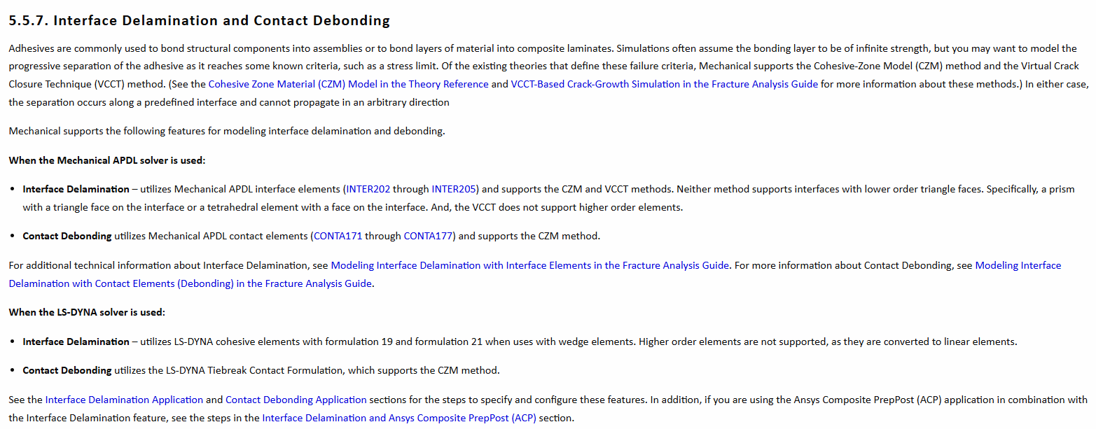
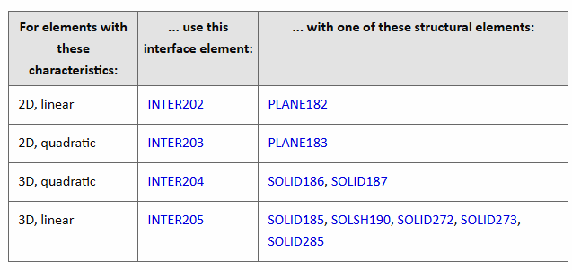
https://ansyshelp.ansys.com/public/account/secured?returnurl=/Views/Secured/corp/v251/en/wb_sim/ds_geo_delam_debond.html
(Mechanical user guide –> Analysis types –> Fracture analysis)
As you said, Interface delamination through INTER elements is not available for shell elements.
https://ansyshelp.ansys.com/public/account/secured?returnurl=//Views/Secured/corp/v251/en/ans_frac/strmodintdelam.html
However, you can do interface delamination through contact elements. Shell elements can use CONT174 elements.
https://ansyshelp.ansys.com/public/account/secured?returnurl=///Views/Secured/corp/v251/en/ans_frac/strmoddebond.html
(fracture analysis guide–> Chapter 3: Crack-Initiation and -Growth Simulation, Interface Delamination, and Fatigue Crack-Growth )
Debonding with contact elements has the following advantages over delamination with the interface elements:
Parts forming the interface can be meshed independently.
Existing models with contact definitions can be easily modified for debonding.
Standard contact and debonding can be simulated with the same contact definitions.
Debonding can be used for various applications (for example, delamination, spot weld failure, and stitch failure).(Contact technology guide–> Debonding) https://ansyshelp.ansys.com/account/secured?returnurl=/Views/Secured/corp/v251/en/ans_ctec/ctec_debonding.html?q=debonding%27
Regards
Shashidhar, PhD
-
January 29, 2025 at 6:57 am
Akshay Singh
Ansys EmployeeHello Dennis,
For debonding, a separate material model needs to be created and used - 'Separation Distance based Debonding' or 'Fracture Enegies based Debonding'.
And the same needs to be selected in the contact debonding object in mechanical.I would like to highlight a couple of points in context of usage of shells:
The analysis type must be set to 2D on the project schematic under Geometry proeprties
Also, please ensure that the geometry lies in the XY plane for performing the 2D analysis.
If the contact debonding object is underdefined even after defining all settings correctly, click on Home Tab> Tools> Show Errors to debug the issue.Example:
-
- You must be logged in to reply to this topic.
-
2607
-
938
-
812
-
599
-
591
© 2025 Copyright ANSYS, Inc. All rights reserved.