TAGGED: divergence
-
-
August 12, 2024 at 10:12 pm
Fakhriyya Mammadova
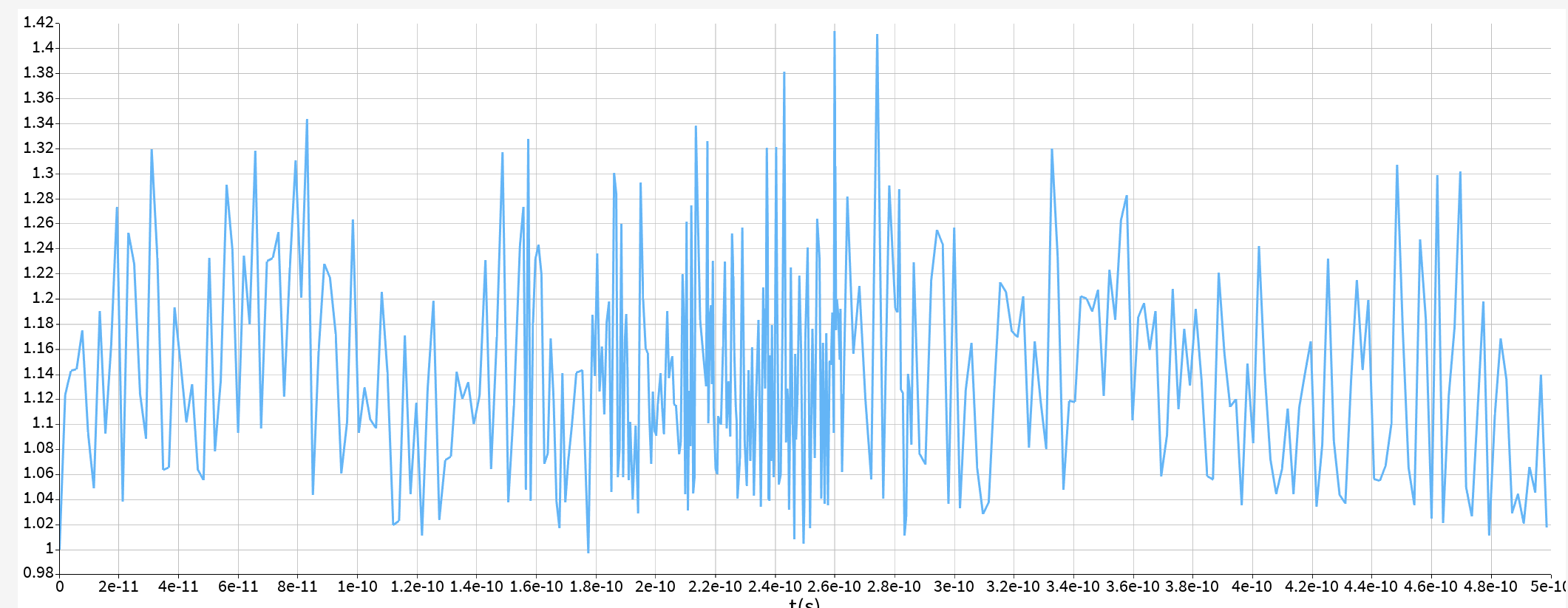
SubscriberHello. I am trying to see if the reason of divergence for my simulation in 3d fdtd is PML layers. For this purpose, I switched all layers to Metal and started the simulation. The status of the resulting simulation is 1, so I decided to visualize the autoshutoff level data. This is what I get. Does it mean that it is still diverging or not?

-
August 13, 2024 at 10:15 pm
Amrita Pati
Ansys EmployeeHi Fakhriyya,
We typically say that a simulation is diverging when the energy inside the simulation keeps increasing exponentially. I wouldn't quite call this divergence. But ideally, the energy should gradually reduce through the simulation and reach a value of 1e-05, at which point the simulation would terminate, and you can extract your results. It is hard to predict where these oscillations are coming from. It could just be that you are simulating something at resonance, where it takes a long time for the energy to decay and at the same time, the metal Boundaries which are not as effective at absorbing the EM waves as PML, are contributing the overall energy of the simulation by reflecting some of the fields back. Could you provide a bit more information on what you are simulating? Maybe a screenshot of the geometry would also help.
Another thing you can do is, change back to PML and run the simulation with a Movie monitor. This would record the fields through out the simulation. If you play the movie monitor, you could most likely identify which region in the simulation is where the local growth in the field takes place.
Regards,
Amrita-
October 27, 2025 at 9:54 am
leonieelsa56
SubscriberGood plan - looks thorough and practical. A couple quick additions: double-check the CFL/time step and mesh at metal edges, enable a global energy monitor so you can see exactly when growth starts, and try adding small material loss (loss tangent) to break stubborn resonances. If the Movie shows a hotspot, post a screenshot of that region and the solver settings (time step, mesh min, PML thickness) and we can pinpoint it faster.
By the way, if you want to take a short break from simulation work, you might enjoy some light entertainment with Kuku TV Mod APK, which offers movies, shows, and reels in a smooth, ad-free experience. You can check it out here: https://kukutvapk.com.
-
-
August 14, 2024 at 12:00 pm
Fakhriyya Mammadova
SubscriberHello Amrita, thank you for your response.
I am simulating a ring resonator. I will describe shortly what I did below.
I started with some gap btw ring and waveguide and was running 3d fdtd simulations, while gradually increasing the gap. These simulations were not diverging until I reached 300nm gap. Now, no matter what I do I cannot resolve divergence.
Here are the steps I took trying to resolve it (none of them worked):
1)I switched to metal to see if the reason for divergence is pml. It gave the picture I posted initially
2)Because of the picture I thought that it is either not because of pml but because of dt stability factor or the reason is actually pml layers but the simulation with metal boudaries needs more time to catch it.
3)I put the time monitors from which I saw that energy starts increasing exponentially at the through port (I use ports in 3D FDTD).
4)I gradually was running the simulations and decreasing the dt stability factor form 0.99 to 0.5, but none of its values resolved divergence.
5)Next, I decided to increase PML layers and alpha. I first switched from standard to stabilized; it didn't work, so I switched to custom and continued gradually increasing the number of layers and alpha. Nothing I tried could resolve divergence.
-
August 14, 2024 at 11:39 pm
Amrita Pati
Ansys EmployeeHi Fakhriyya,
It looks like you have already covered most of the troubleshooting strategies. Would you be able to run this simulation for a single wavelength and let me know if you still see the divergence? Let me think of some other ways to test this.
Regards,
Amrita
-
- You must be logged in to reply to this topic.


-
4512
-
1494
-
1386
-
1209
-
1021

© 2025 Copyright ANSYS, Inc. All rights reserved.


