-
-
February 20, 2023 at 4:46 pm
Mohtasim Hamid Pial
SubscriberI am designing a 4 turn toroid shape inductor on a polyimide susbtrate in order to study the inductance vs frequency graph. The core is a cobalt based alloy and it was added. Generally the inductance should drop to zero at higher frequencies but my model dose not have that drop. I ran the simulation upto 100GHz. What the reason for it ? Currnet applied: 1A
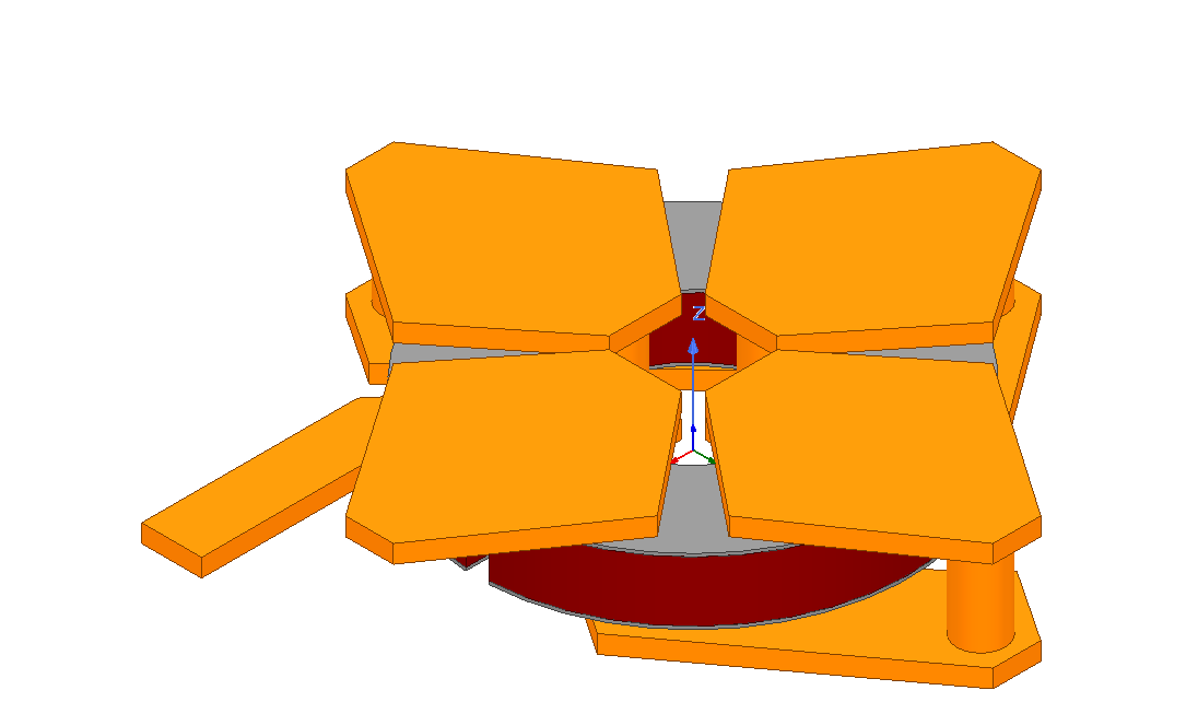
INDUCTOR DESIGN
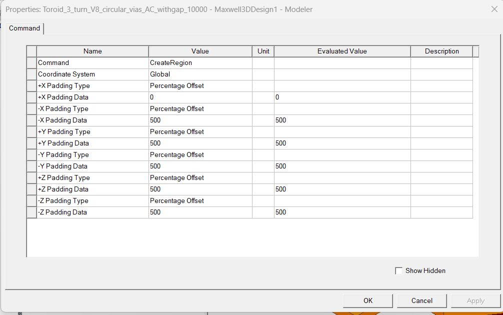
BOUNDARY REGION
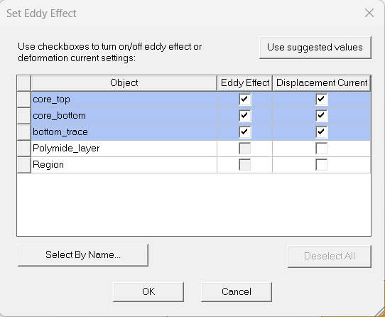
EDDY EFFECTS:
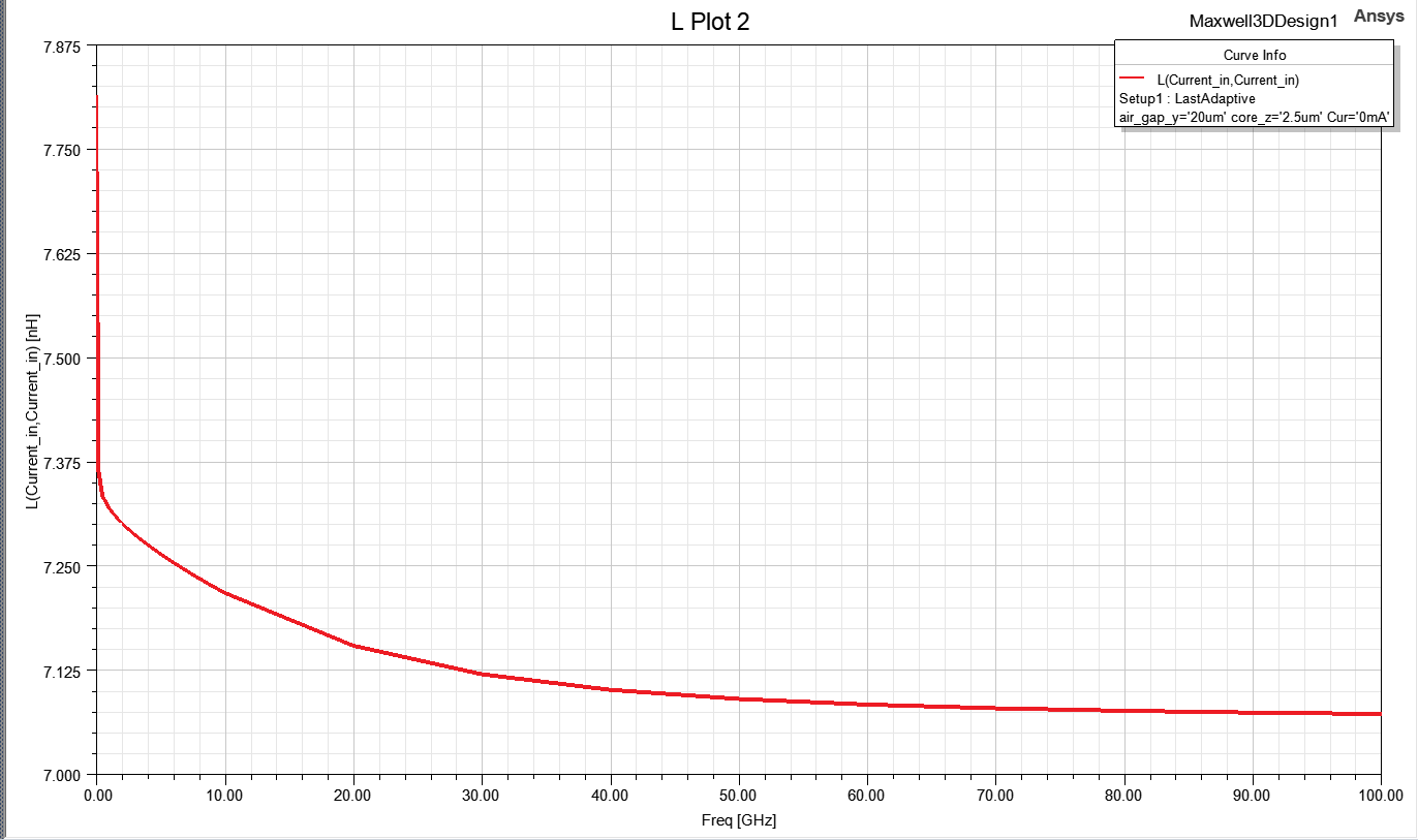
SIMULATED RESULT: (L vs F)
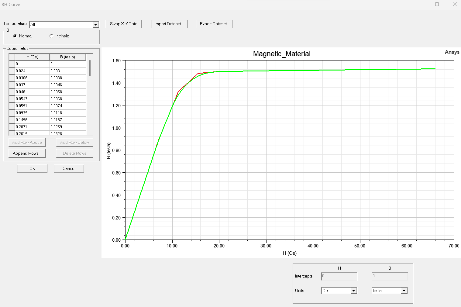
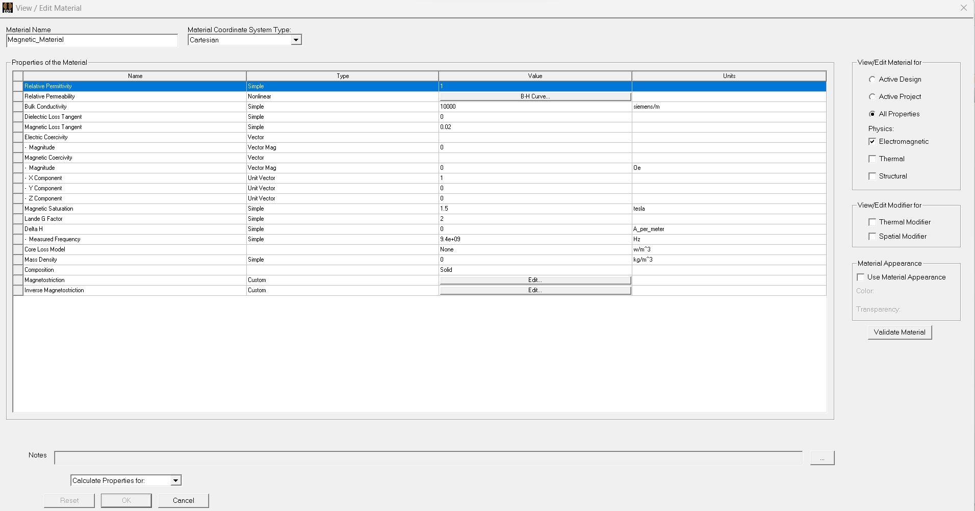
CORE PROPERTIES
-
February 24, 2023 at 12:16 pm
NKC
Forum ModeratorHi mh.pial5,
Why do you think inductance should drop to zero at higher frequencies? It is inversely proportional to the frequency. Do you mean absolute zero?
What is your reference here?
Regards,
Navya
-
Viewing 1 reply thread
- The topic ‘Discrepancy in Inductance Simulation for an Toroid Inductor in ANSYS MAXWELL (’ is closed to new replies.
Innovation Space


Trending discussions


Top Contributors


-
4688
-
1565
-
1386
-
1242
-
1021
Top Rated Tags


© 2025 Copyright ANSYS, Inc. All rights reserved.
Ansys does not support the usage of unauthorized Ansys software. Please visit www.ansys.com to obtain an official distribution.

