

TAGGED: ansys-maxwell, eddy-current, inductance, maxwell
-
-
June 11, 2021 at 7:07 pm
tawhidtarek
SubscriberI have run an eddy current simulation for an actuator in Ansys Maxwell. The main target was to observe the coil inductance with respect to the frequency. We got our result in the simulation. However, when we verify the result with the experimental one, they do not match at all. I have checked the material properties and dimensions of the .aedt file. But still, I have not been able to find out the reason behind this huge discrepancy.
June 16, 2021 at 3:00 pmDELI
Ansys EmployeeHi, this is a pretty big difference, could you tell us more detail about this design?
is the coil design the same as real test? dimension, geometry, the number of strand.
is the core design matching with real test?
Is the excitation matching the real test? Is there any saturation on the core?
How is mesh? Mesh quality would affect calculation accuracy.
is there any movement in real test? If yes, does it include spring force and/or friction? Eddy Current solver is a steady state solver which will not consider motion.
June 23, 2021 at 7:17 pmSubscriberThe coil design is the same in terms of dimension, geometry, and the number of strands.
The core is also the same.
The excitation is also matching the real test. You can find the equivalent circuit of the test in the attachment.
The mesh quality is also good. I have checked the mesh statistics under solution. The standard deviation is in the range of e-11. The picture of the mesh has been attached.
There is no movement in the real test. The terminals of the coil were connected to the inductance measurement device.
June 23, 2021 at 8:25 pmSubscriberHy,
Just to add, there was no saturation in the core in the simulation. And we have used HP4194A Impedance Analyzer to measure the inductance in different frequencies.
Regards Tarek
July 9, 2021 at 5:57 pmAnsys Employee
Mesh looks pretty good, I can see some sort of eddy current from the mesh plot.
Do you have eddy effect on the core in this simulation?
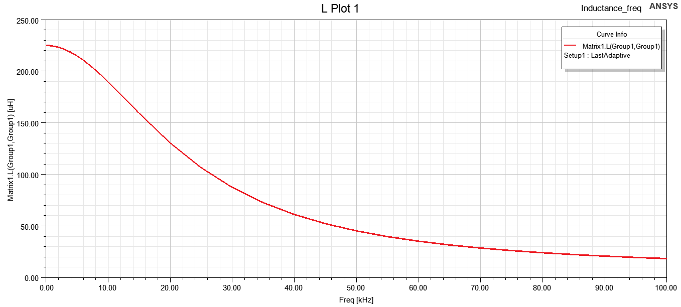
Looking at the plot of L vs Frequency of real test and simulation, it seems the calculated inductance from simulation reacts to frequency change, which looks like eddy effect. However, the experimental L curve doesn't react a lot from frequency change, is the real core laminated?
July 13, 2021 at 5:33 pmSubscriberHy Thanks a lot for your comment. The real core is laminated. In the material properties, I also set the core as laminated in the simulation.
However, the eddy effect was "on" for all the parts in the simulation. I set the eddy effect off the materials except for the magnet . I reran the simulation and now the results look like this:
still, there is a significant difference between the values. Can you please think of any other issues that can cause the difference? Thanks in advance.
Regards Tarek
Viewing 5 reply threads- The topic ‘Discrepancy in Inductance Calculation for an Actuator’ is closed to new replies.
Ansys Innovation Space Trending discussions
 Top Contributors
-
peteroznewman
 3597
3597 -
scabo
 1283
1283 -
Dennis Chen
 1117
1117 -
javat33489
 1068
1068 -
Shyam Prasad V Atri
983
Top Rated Tags
© 2025 Copyright ANSYS, Inc. All rights reserved.
Ansys does not support the usage of unauthorized Ansys software. Please visit www.ansys.com to obtain an official distribution.
-


The Ansys Learning Forum is a public forum. You are prohibited from providing (i) information that is confidential to You, your employer, or any third party, (ii) Personal Data or individually identifiable health information, (iii) any information that is U.S. Government Classified, Controlled Unclassified Information, International Traffic in Arms Regulators (ITAR) or Export Administration Regulators (EAR) controlled or otherwise have been determined by the United States Government or by a foreign government to require protection against unauthorized disclosure for reasons of national security, or (iv) topics or information restricted by the People's Republic of China data protection and privacy laws.


