TAGGED: frame-motion, interface, mesh-motion, mrf, propeller, propeller-rotation, rotate-mesh, sliding-mesh
-
-
May 2, 2024 at 6:18 pm
jimmyhilbert098
SubscriberHello and thank you for reading my post,
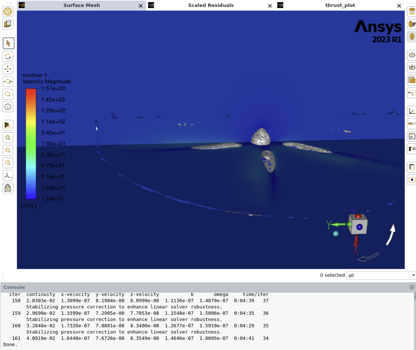
I am simulating an Isolated Propeller with a Frame Motion (Stationary Case) and Mesh Motion (Transient Case) in Fluent 2023 R1 and I am encountering in both Cases that there is a discontinuity at the Interface between both regions. I my Figure below one can see the Q-Criterion (with Axial Velocity) and that the tip vortices form as they should inside that Rotating Region. But as soon as the vortex hits the Interface, it seems that the vortex looses it's rotating characteristic and just moves straight downstream. Normally the tip vortices should kind of spiral downwards. Â
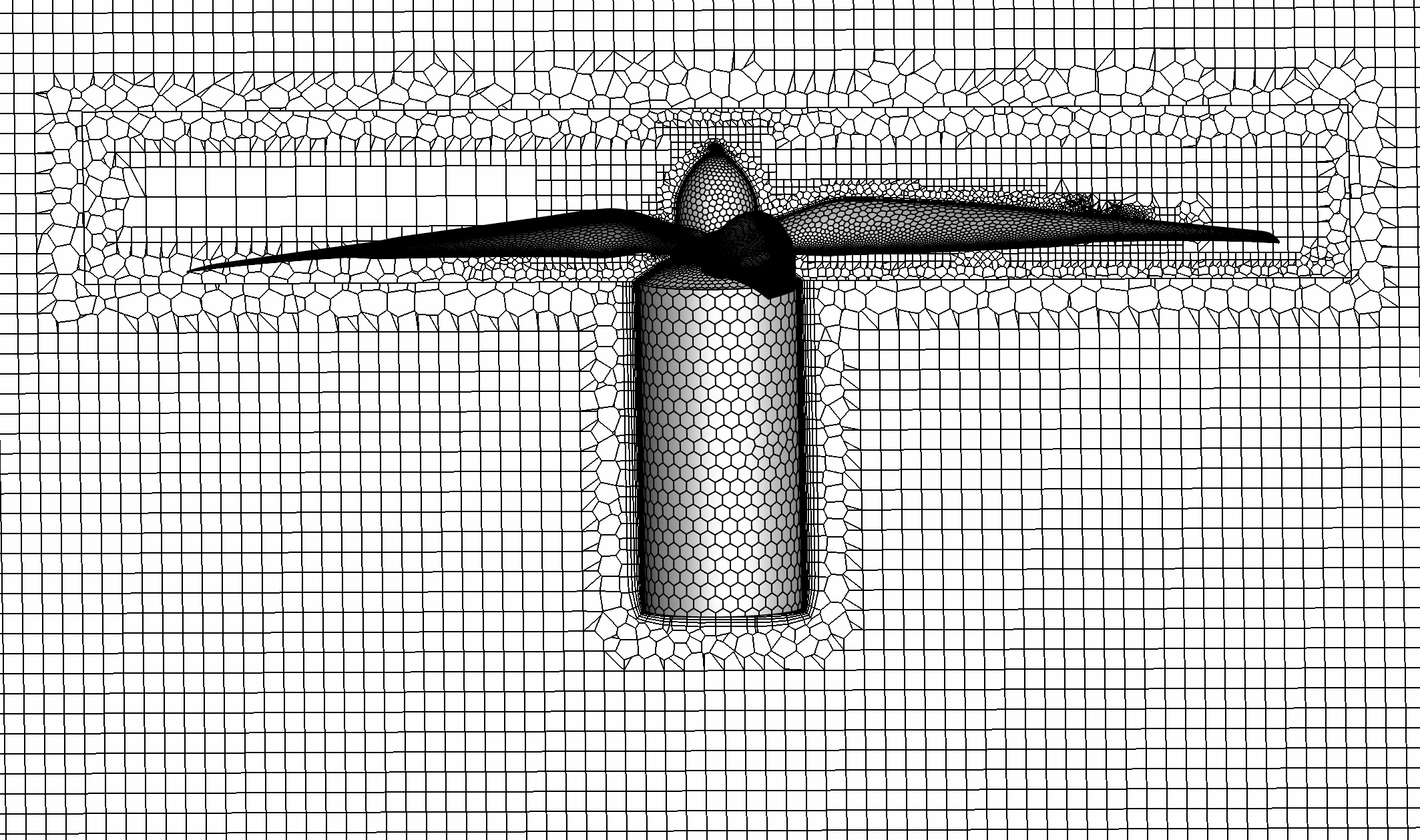
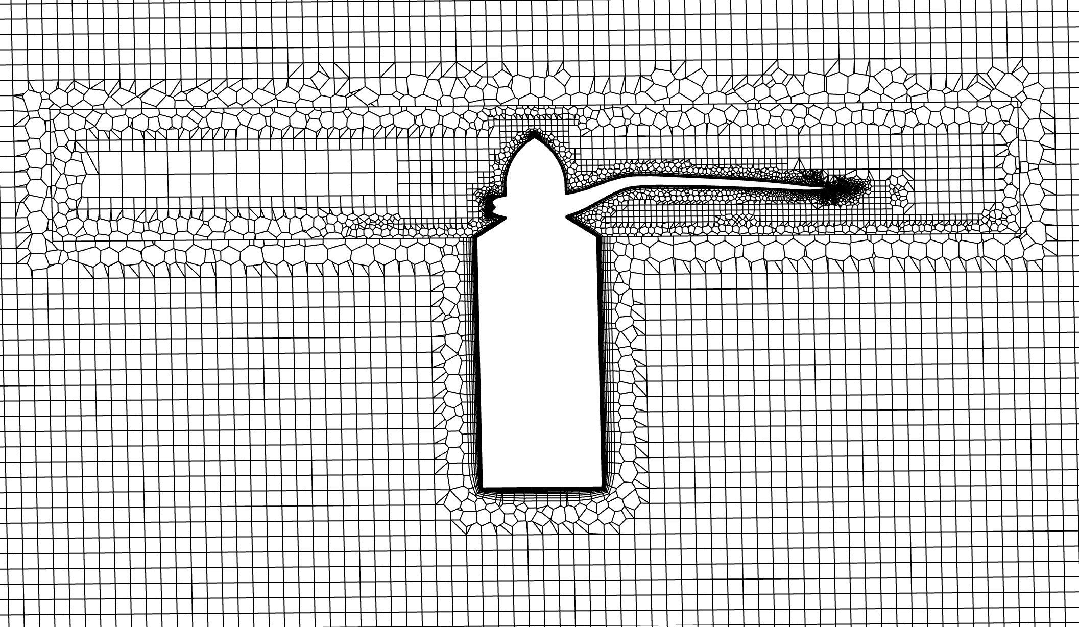
I meshed my Stationary Domain and Rotating Domain individually. Then I merged both meshes in Fluent (first load one mesh in, then append the other). I manually created the Interface between both Regions, defined the Rotational movement for my rotating Region. In both Stationary and Transient cases, the vortices behave as in the figures below.
The simulation from the figures contained the coarsest mesh of all, however the problem consists also in very fine meshes with very good quality. Max Skewness: 0.63, Min Orthogonal Quality: 0.20. No difference in cell size at the interface in both meshes.
Thanks a lot and let me know if there is anything you'd need to know for helping.
-
May 3, 2024 at 9:30 am
Rob
Forum ModeratorPlease can you post an image of the two interface zones? Just want to check mesh uniformity in the circumferential direction on both sides.Â
-
May 6, 2024 at 4:56 pm
jimmyhilbert098
SubscriberDear Rob, thank you for your answer. I hope I correctly understood your demand. Here are pictures of the mesh on a slice through the center of the propeller.
As you can see, it is a non-conformal mesh as I merged both meshes in fluent. At an earlier stage I meshed both the stationary and rotating domain together, having a conformal mesh. However, for some reason fluent created holes in that mesh interface which lead to a divergence in the continuity resdiuum (see the contour plot I uploaded). That is the reason why I mesh both geometries separately, naming the interface area "interface". Then I manually create the interface in fluent
Â
-
May 7, 2024 at 9:29 am
Rob
Forum ModeratorThe holes may just be a contour plotting issue. The mesh looks OK, albeit the jump in cell size isn't ideal. Can you plot the Q-criterion on planes with node values off so we can see another field? The fact that the model has the stability warnings isn't good, so I'd be wary of trusting the results.Â
-
- The topic ‘Discontinuity at Interface between Rotating and Stationary Domain’ is closed to new replies.
- How do I get my hands on Ansys Rocky DEM
- Unburnt Hydrocarbons contour in ANSYS FORTE for sector mesh
- convergence issue for transonic flow
- Facing trouble regarding setting up boundary conditions for SOEC Modeling
- Point exception in erosion calculation
- Errors with multi-connected bodies using AQWA
- Script Error Ansys
-
2542
-
933
-
792
-
599
-
591
© 2025 Copyright ANSYS, Inc. All rights reserved.