-
-
October 4, 2023 at 1:37 am
Mahmoud Mostafa
Subscriber -
October 12, 2023 at 8:56 pm
Dan Dv
Ansys EmployeeHello Mahmoud,
I was checking with my colleagues on this, and we can't really give much advice at this point without seeing the model in question. If you are a full customer, would you be able to open a support ticket so that we can be of further assistance?
-
October 13, 2023 at 4:27 am
Mahmoud Mostafa
SubscriberHi Dan, I already asked customer support by email and they are the ones who referred me to this forum.
-
-
October 13, 2023 at 4:08 am
Irina G.
Ansys EmployeeHello Mahmoud,
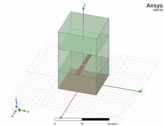
I tried to reproduce the behavior with the simple diode in array based on yout picture, and I don't see the behavior - the current plots are the same, independent of scan angle. In my array, dipoles are in the open and not touching each other, radiation on top and bottom. Is your array similar?
-
October 13, 2023 at 4:22 am
Mahmoud Mostafa
SubscriberHi Irina, it is a ground plane at the bottom of the unit cell in my case, but It isn’t the cause of the problem, without it still dipole currents are discontinuous at lumped port edges
-
-
October 13, 2023 at 4:18 am
Mahmoud Mostafa
SubscriberI have a CMC account "https://www.cmc.ca/", where I get my license from.
-
October 16, 2023 at 5:17 pm
Irina G.
Ansys EmployeeHi,
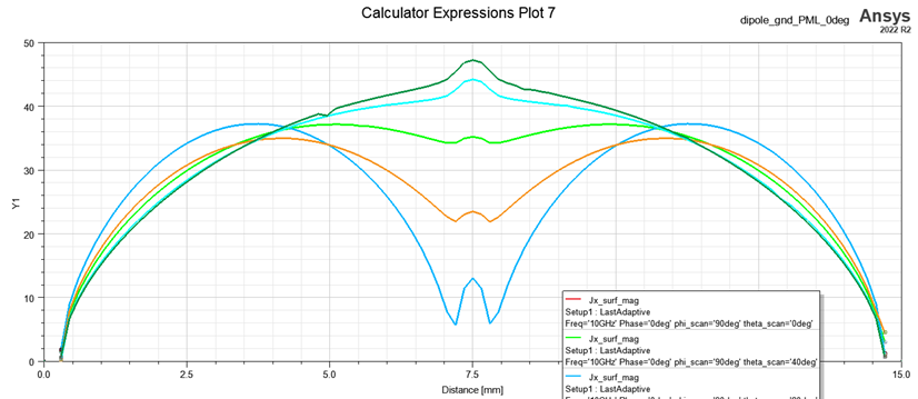
I can reproduce the change in current pattern while scanning the phase. I think it's normal. S-parameters are expected to change with the different phase sgift in Latice pairs. Big change means stronge coupling between the dipoles in the array; field distribution is expected to change. The current distribution is no exception. If you move dipoles in the array further apart (increasing the size of the Unit Cell), you will decrease the coupling and should see smaller changes in field distribution.
In general, why are you looking at current distribution? What is the goal of simulations to begin with? Is the solution you get from HFSS doesn't align with your prediction/expectations?
-
October 16, 2023 at 10:09 pm
Mahmoud Mostafa
SubscriberHi Irina, my issue isn't the change in current distribution while scanning...my problem is the discontinuity in current at lumped port edges even at boresight...it just is getting worse when the scanning angle increases
-
-
October 17, 2023 at 7:10 pm
Irina G.
Ansys EmployeeMahmoud, thanks for clarifying the issue. I hope this one is easier to explain. It looks like you plot X projection of surface current along the line. The dipole arms has some width. Plot the same surface current across the dipole strip at several places and you see that the current is not uniform but increased at the edges. The distribution across the port can depend on the shape of the port (width vs. length), the width of the dipole and the mesh quality. This distribution can be slightly different from distribution across the dipole width - port has different formulation than PerfE BC in terms of fields. Plot the mesh and surface current on dipole and port. I prefer to have at least 10 mesh elements across the dipole width and alnog the port.
I want to repeat the question: why current distribution is so important for you? What is the simulation goals? The model itself involves a lot of "ideal" features. Based on simulation goals, you may need to include more realistic features like finite thickness and material properties.
The lumped
-
October 27, 2023 at 11:54 am
Mahmoud Mostafa
SubscriberThanks for your reply, I had it simulated at a refined mesh of max element length =lambda/600, the issue of discontinuity of current at the lumped port is there with or without fine mesh. Regarding your question, the study of how the current varies with scanning angle is part of my research on phased array antennas. I am just starting with an ideal simple model but I am facing this issue which doesn't make sense. Even at boresight, there is a slight discontinuity although the current distribution should be a perfect cosine function
-
-
- The topic ‘Dipole surface current problem with lumped port’ is closed to new replies.


-
4673
-
1565
-
1386
-
1236
-
1021

© 2025 Copyright ANSYS, Inc. All rights reserved.


