-
-
February 27, 2023 at 1:44 pm
xinglong.wu
SubscriberDear all,
I noticed that if we put the dipole (Hertzian-dipole excitation) close to the ground and I measured the E-field at one point far from the dipole, the simulated E-field is different from the one I obtained by using image method.
Specifically, I did the following HFSS simulations and I noticed some differences
Working frequency: 200 MHz. E-field observation point P1: (0, 0, 400) mm
Working space: free-space with a XY perfect conductor (PEC) plane at z = 0 mm.
HFSS case #1: One dipole in a free-space space with a XY perfect conductor (PEC) plane at z = 0 mm.
Dipole information: +y E Hertzian dipole, L=50 mm, Radius: 5 mm, location (0, 0, 30) mm (30 mm above the PEC plane.
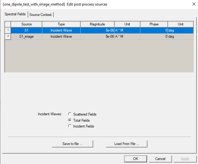
HFSS case #2 (image method): Two dipoles in a free-space space.
Dipole information :
1. +y E Hertzian dipole, L=50 mm, Radius: 5 mm, location (0, 0, 30) mm.
2. -y E Hertzian dipole, L=50 mm, Radius: 5 mm, location (0, 0, -30) mm
It is observed that the total E-field at P1 generated in case #1 and #2 are difference.
My questions is:
1. Why the differences are observed in Case #1 and Case #2 when the same setting is considered (same working space, same setting for analysis, etc.)
-
March 2, 2023 at 1:43 pm
Praneeth
Ansys EmployeeHi Xinglong,
Thank you for reaching out to us.
Please see my observations / comments from your post:
- Did you check "infinte ground plane" while setting the PEC boundary condition in Case-1?
- Did you excite both the antennas for case-2? Please share the edit sources dialog box for case-2 simulation.
Please share screenshots of the simulation geometry and setup to help us serve you better.
Best regards,
Praneeth. -
March 5, 2023 at 9:48 pm
xinglong.wu
SubscriberHi! Praneeth,
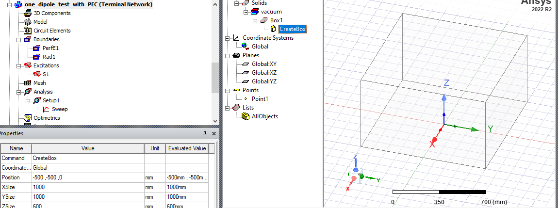
Regarding the simulation geometry and setup, The setings for the two cases are similar.
The solving space Box1 size: Position: (-500, -500, 0); (Xsize, Ysize, Zsize) = (1000, 1000, 600). It is larger than the suggested size: Lambda/4.
Solution types: HFSS-Network Analysis-Terminal (ANSYS 2022 R2)
Analysis Setup: Freq = 4 GHz, Maximum number of passes: 20, Maximum Delta Energy: 0.1. Others: Default. Sweep: discrete-single point at 200 MHz.
A screenshot:
It is also noticed that the sizes of the solving space can affect the result of case 1, but cannot affect the result of case 2. The result of case 2 is constant and is always equal to the one obtained from the theoritical calculations. Therefore, I guess the difference is due to the pec GND of case 1. But I don't know the reason.
I hope the information is enough and I look forward to your feedback/suggestions.
Thanks and best regards,
Xinglong
-
September 27, 2023 at 3:09 pm
Praneeth
Ansys EmployeeHi Xinglong,
We appreciate your patience on this query and thanks for reminding us to provide the response.
Please find the following suggestions/recommendations based on the details provided so far:
- It is mentioned that the results of case 1 are changing with the size of the solution space. It looks like you are explicitly defining an air region and assigning a radiation boundary to it. Please note that it is recommended to have at least quarter of the wavelength distance between the radiating element and the boundary surface. You can use auto open region option available in the solution type window. Please check once.
- Are you assigning perfect E boundary to the bottom of the air region? I do not see any sheet object defined in the model history tree. If that is the case, please create one sheet with the required dimensions and assign perfect E boundary condition (as the position of the box face will be changed as per point1).
- It looks like the observation point falls under near-field region for the said frequency (200 MHz). Are you looking at the near-field calculations?
Kindly check the above points.
Best regards,
Praneeth. -
September 28, 2023 at 7:19 am
xinglong.wu
SubscriberHi! Praneeth,
Thanks for the follow-up.
Regarding question #1: I can quote my previous information:
"The solving space Box1 size: Position: (-500, -500, 0); (Xsize, Ysize, Zsize) = (1000, 1000, 600). It is larger than the suggested size: Lambda/4." ,
"Dipole in formation: +y E Hertzian dipole, L=50 mm, Radius: 5 mm, location (0, 0, 30) mm (30 mm above the PEC plane."
f = 200 MHz in free space -> Lambda/4 = 375 mm. The distance between radiating element and the boundary surface = 495 mm > Lambda/4.
Regarding question #2: You can see in my previous photo, there is a PerfE1 boundary. This is the perfect E boundary to the bottom of the air region.
Regarding question #3: The dipole theory works in both near-field and far-field regions, as proved by the comparison betwwen case #2 and the theoritical calculations. So, I don't think it is important. Do we need to pay special attention to anything when using HFSS for near-field or far-field simulation with dipoles?
I would be also available to share the HFSS project if you provide cloud space to upload it. Alternatively, if you could try to simulate the above cases, I think you will see the difference.
Thanks and I will look forward to your reply.
Best regards,
Xinglong
-
October 10, 2023 at 11:41 am
Praneeth
Ansys EmployeeHi Xinglong,
Thank you for posting the reply to the questions. Your patience on this is much appreciated.
It looks like your model has to be reviewed for a faster resolution. But, it is not possible to access your model over the forum because of the forum rules. Please raise a service case if you have access to service for better guidance.
Best regards,
Praneeth.
-
- The topic ‘Dipole simulation with HFSS’ is closed to new replies.


-
5094
-
1831
-
1387
-
1248
-
1021

© 2026 Copyright ANSYS, Inc. All rights reserved.


