TAGGED: polyflow
-
-
January 31, 2024 at 6:21 pm
Fabian Braun
SubscriberPolyflow ????: I hope you can assist me with some questions regarding my current project. In a melt channel, polypropylene flows through a rotating bolt with a transverse bore. The rotating bolt is rotatable and can be locked in four different positions at 10, 20, 30, and 45 degrees. At this point, I still need help in various areas:
a) In the "Create a sub-task" section, the options for "Flow Problems" are available. For all choices, such as "Simplified Viscoelastic Non-Isothermal Flow Problems," an error message occurs when reading the material, preventing the action from being executed. Question: Can only "Generalized Newtonian isothermal flow problem" be selected?
b) My test material is "Virgin PP with MFR = 20 … 25 g/10 min." For example, the used material PP.513 has an MFR of 70 g/10 min. Question: How can I adjust the MFR of the material?
c) In the "Inflow calculation on Inleet" section, the volumetric flow rate is adjustable. The defined parameters do not match the results in the "Streamline" section. For example, selecting 0.5 m/s shows 0.4 m/s under "Velocities." Question 1: How is this related? Question 2: Is it possible to set the temperature (450°C) of the plastic melt?
d) To simulate the flow pattern, the "Fluid Wall" was created. Creating a semi-open rotating bolt, where one half is flowing through and the other half flows along the surface of the rotating bolt, does not work. (to simulate dead points, turbulence, and material wear) Question: Are only complete flows possible?
e) A flawless flow pattern is displayed when there is a large flow entry from the melt channel into the transverse bore of the rotating bolt. However, with a narrow flow entry (i.e., 10°, 20°, and 30°), the simulation stops upon entering the transverse bore. Question: Is the simulation stopping due to the narrow flow passage?
f) Is there a setting to simulate the temperature profile, i.e., the behavior of temperature during flow?
-
February 1, 2024 at 4:19 pm
Prashanth
Ansys EmployeeHello there
-- I think moving part cases only supports generalized Newtonian model
-- You can adjust the flow boundary conditions?
-- Maybe the velocity at the inlet is in parabolic distribution. Also, you can use non-isothermal model for setting temperature boundaries.
-- Maybe a diagram to add to the context
-- Make sure there is enough cells between walls to avoid resistance from no-slip walls
-- Again, are you using non-isothermal model?
We have a non-isothermal twin screw extruder (eg_47) in examples page that might be helpful.
-
February 4, 2024 at 7:08 am
Fabian Braun
SubscriberThank you for your response.
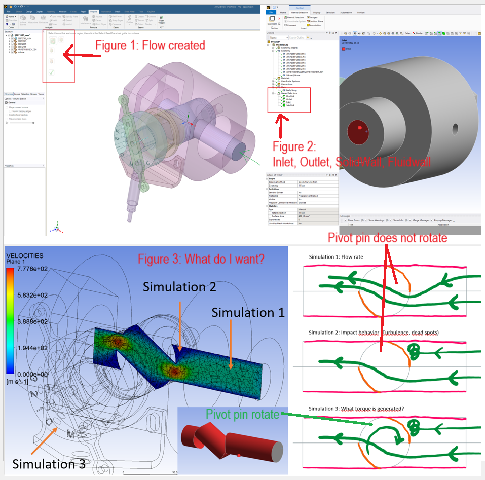
The first image is for general understanding. See Figure 1.
I want to simulate three scenarios (at settings of 10, 20, 30, and 45 degrees).
Simulation 1: Flowrate (partially working) (rotary pivot does not rotate)
Simulation 2: Impact behavior (Turbulence, dead spot) (rotary pivot does not rotate)
Simulation 3: What torque is generated? (rotary pivot rotates)
Response to your/my question:
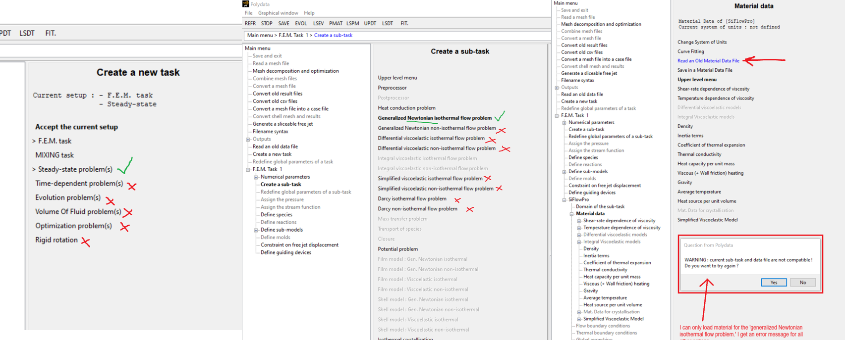
a) All material choices result in an error message, except for "Generalized Newtonian isothermal flow problem" (also for "non-isothermal"). "Warning: current sub-task and data file are not compatible!" The simulation cannot be started. See Figure 2.
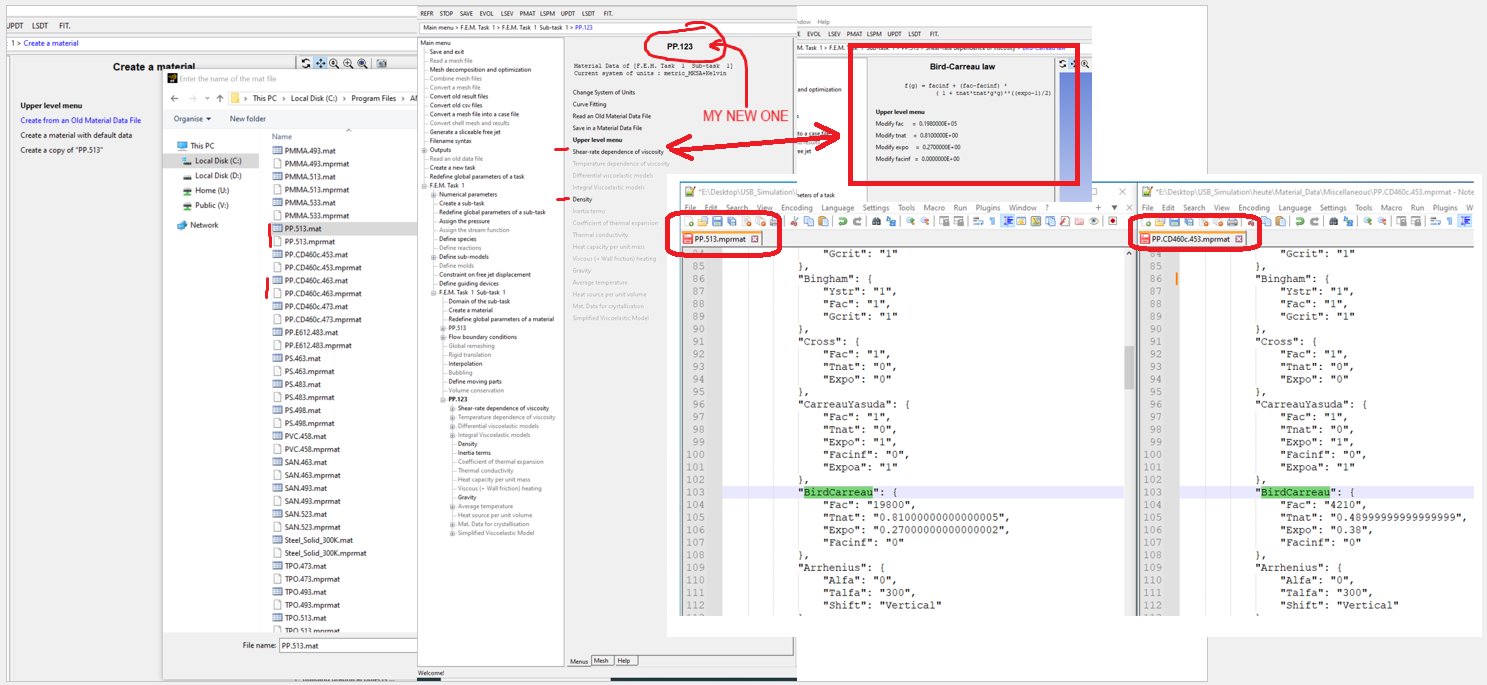
b) Material definition: Two file types are provided. The first program consists of 680 characters, and the second program consists of 430 characters. I compared the program code. In the first program, the code is identical except for "BirdCarreau" and "Density."
When I copy the material in the "Sub-Task" to create my own material, I can set values for "Density" and "Shear rate."
Under "Shear-rate," I can adjust the value for "BirdCarreau." Adjusting the second program is not possible or I haven't found it.
I haven't found a direct conversion to MFR in any book or literature. However, MFR is crucial for defining the material. See Figure 3.
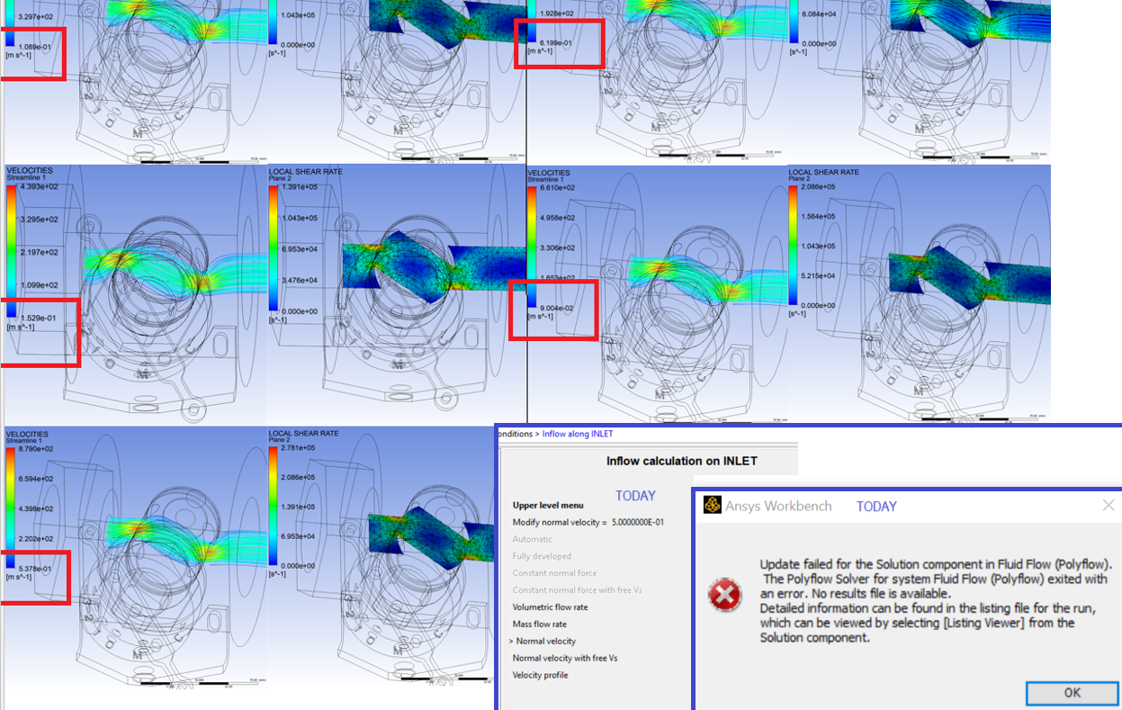
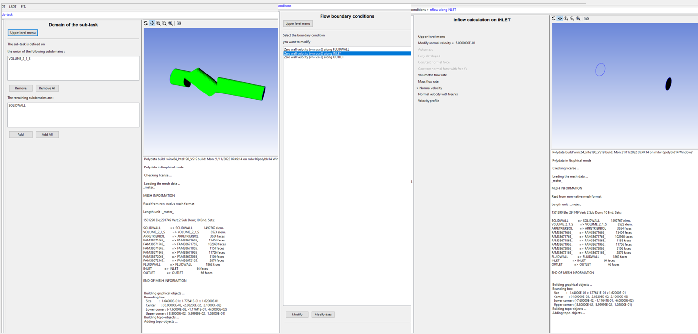
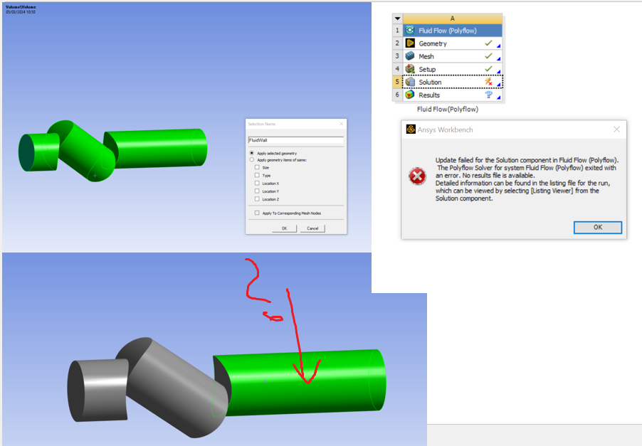
c) As mentioned, Simulation 1 has partially worked, as seen in Figure 4. The velocity results (1.089e-01, 1.529e-01, 5.378e-01, etc.) are odd and do not match the input values. Today, I wanted to test it again, but an error message occurred (see Figure 4).
e) Your recommendation to reduce the mesh size makes sense. Unfortunately, I cannot test it; the same error message appears as in "Figure 4, bottom right."
In Figure 5, the "flow boundary conditions" are shown.
g) Regarding Simulation 2: Impact behavior (Turbulence, dead spot)
In "SpaceClaim," I can only select the entire flow contour. Is it possible to select only the first surface as "FluidWall"? A simulation was not possible, see Figure 6 and Figure 1.
h) Simulation 3: What torque is generated?
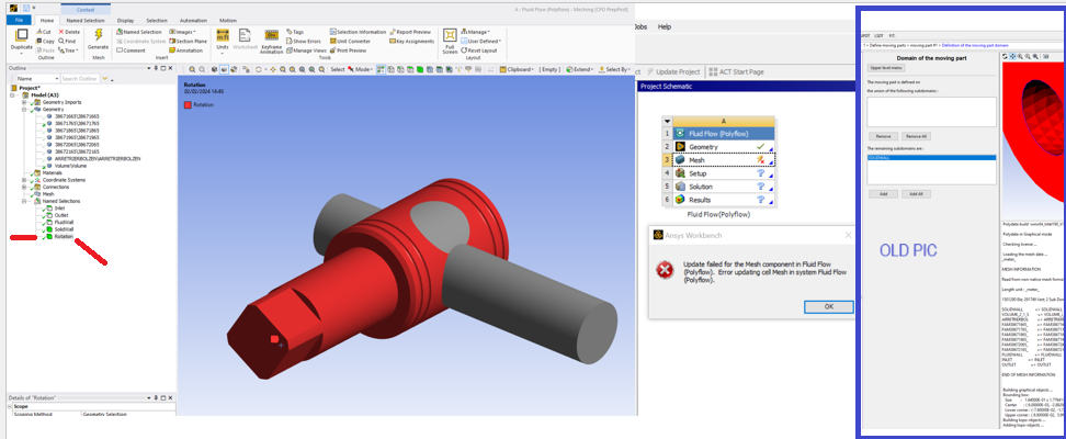
I selected the rotary pivot in addition to "Inlet, Outlet, FluidWall, and SolidWall" and labeled it as "Rotation" to be able to select it under "define moving parts." I cannot access the setup, see Figure 7.
As you can see, I have already delved into the problems extensively. I hope you can help me. Thank you.
-
February 4, 2024 at 7:11 am
-
February 4, 2024 at 7:12 am
-
February 4, 2024 at 7:13 am
-
February 4, 2024 at 7:15 am
-
February 4, 2024 at 7:16 am
-
February 4, 2024 at 7:17 am
-
February 4, 2024 at 7:19 am
-
- The topic ‘different questions’ is closed to new replies.


-
4838
-
1587
-
1386
-
1242
-
1021

© 2026 Copyright ANSYS, Inc. All rights reserved.

