-
-
May 10, 2023 at 4:03 pm
Navsing
Subscriber
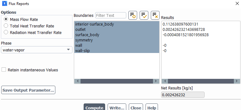
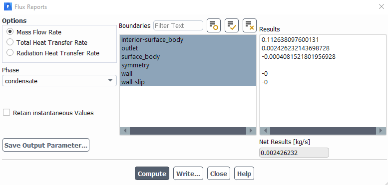
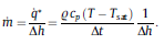
I'm simulating condensation of water on a 2D pipe. I have written a UDF using the DEFINE_MASS_TRANSFER macro to determine the mass transfer rate of the vapour via using an energy balance method which forces the interface temperature to stay at saturation temperature each time step using this law.
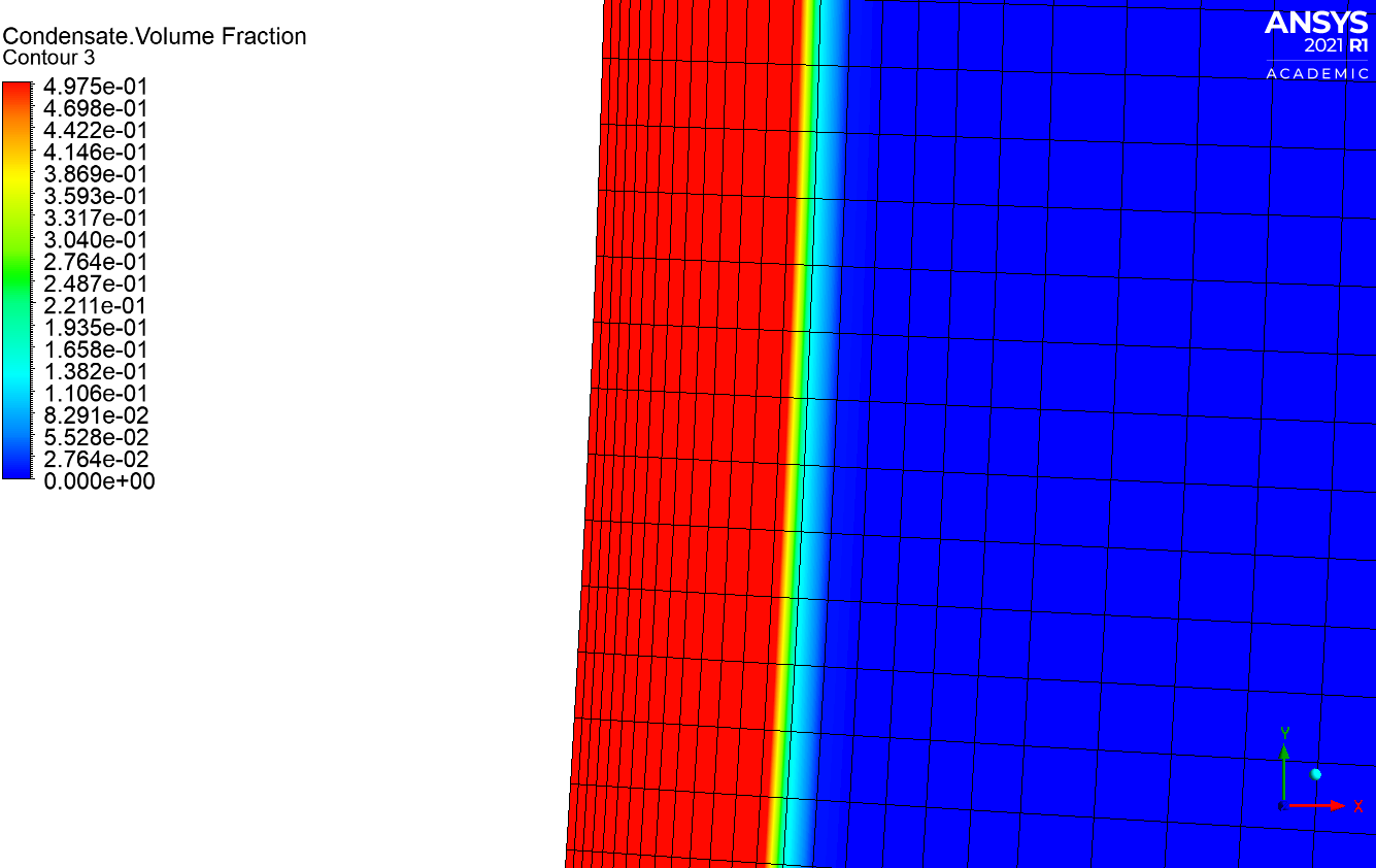
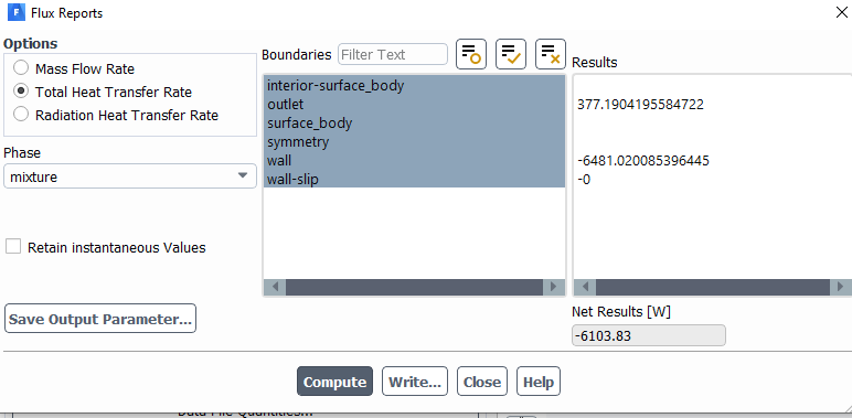
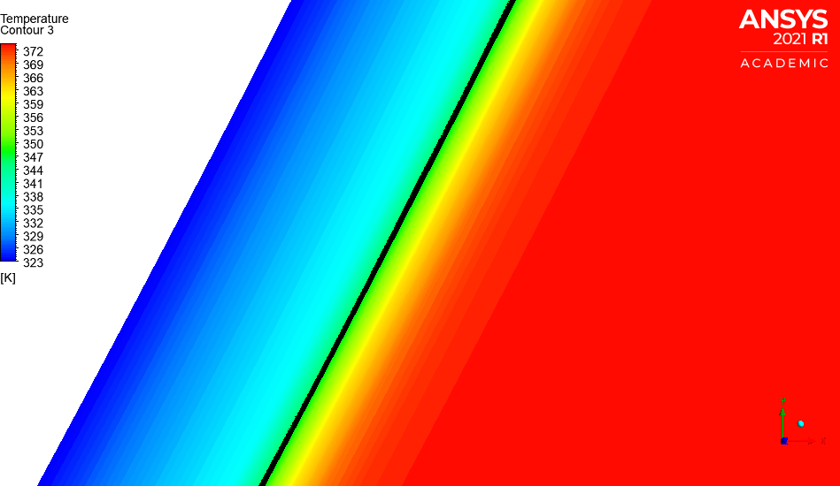
When using the compressive interface tracking method with a slope limiter value of 1, I've manage to validate the film thickness against the Nusselt theory. However my heat transfer coefficient/heat flux values are completly wrong. I obtain a value of around 2500 W/m2K when it should be 9000 W/m2K. I've even set the reference temperature to be equal to saturation. The same can be said for the temperature and velocity profiles. Also, the temperature at the interface does not equal saturation as it is meant to. This can be seen on the picture
Although, when using the geometric reconstruct, the film thickness is much larger than it should be but however, I obtain higher heat transfer coeffcients than I did with the compressive method (4500 W/m2K). And the interface temperature is closer to saturation (369K).
I'm not sure why the interface temperature for the compressive method is much lower than saturation but I obtain the correct film thickness, not to mention having much lower heat transfer coefficients as the heat transfer coefficient is a function of the film thickness due to thermal resistance?
Kind regards.
-
May 11, 2023 at 12:50 pm
Rob
Forum ModeratorHow well refined is the mesh, and how's the convergence looking?Â
-
May 11, 2023 at 3:38 pm
Navsing
SubscriberConvergence and mesh is fine. I also looked at the ansys users guide and said that compressive is typically the best for evaporation/condensation problems due to it being able to capture the diffusive interface as well as the sharp interface. And the slope limiter is essentially the degree of compression at the interface.
Â
Â
-
May 12, 2023 at 10:00 am
Rob
Forum ModeratorHow many cells over the gas/liquid layer?Â
-
May 12, 2023 at 10:51 am
-
May 12, 2023 at 1:04 pm
Rob
Forum ModeratorWhy the 0.5 limit to condensate?
-
May 12, 2023 at 1:06 pm
Navsing
Subscriberits typically the value to determine the interface criteria without interface reconstruction (i.e. geo-recontruct) from reading into the literature.
-
May 12, 2023 at 1:09 pm
Rob
Forum ModeratorIt is, but that's when finding the free surface postion. I take it the condensate volume fraction is 1 at the wall?
-
May 12, 2023 at 1:19 pm
Navsing
SubscriberYes from when post-processing, I take the interface as 0.5. But from the simulation persepective, I think it uses a volume fraction of 1 to determine when the condensate forms.Â
-
May 12, 2023 at 1:49 pm
Rob
Forum ModeratorNot sure. You mention the heat flux is out as well? Does the heat in/out correctly match the latent heat?Â
-
May 12, 2023 at 2:20 pm
-
May 12, 2023 at 2:21 pm
Navsing
Subscriberlatent heat of vapourisation for water is 2257 kj/kgÂ
-
May 12, 2023 at 2:36 pm
Rob
Forum ModeratorCheck gas mass in and gas & liquid mass out. You're trying to see if what goes in comes out again.Â
-
May 12, 2023 at 2:57 pm
-
May 12, 2023 at 3:29 pm
Rob
Forum ModeratorWhere's the inlet?Â
-
May 12, 2023 at 5:08 pm
Navsing
SubscriberThere is no inlet. I just have a pressure-outlet on the outer fluid domain. I initalize the temperature of the fluid domain to be equal to saturation and set the wall temeprature below saturation to create the mass transfer between the vapour and the wall. Â
-
May 15, 2023 at 8:55 am
Rob
Forum ModeratorWith condensation I'd expect flow into the domain as the vapour condenses and temperature drops.Â
-
May 15, 2023 at 9:30 am
Navsing
SubscriberSo I should have a pressure inlet as well as an outlet?
-
May 15, 2023 at 10:02 am
Rob
Forum ModeratorPressure Outlet is fine provided the backflow condition is sensible.Â
-
May 15, 2023 at 10:26 am
Navsing
SubscriberFor the pressure outlet, the backflow conditions for temperature are equal to saturation and has a water-vapor volume fraction of 1.Â
-
May 15, 2023 at 10:35 am
Navsing
SubscriberPlus when checking the velocity vector contours, I do have flow coming into the domain from the outlet towards the tube wall.
-
May 15, 2023 at 10:41 am
Rob
Forum ModeratorÂ
Â
OK. If the temperature in the fluid domain is below saturation temperature you’ve potentially got a problem: read up on the VOF model and how it works.Â
It’s too early, I need more tea. Positive mass flow is into the domain. But you should hit zero when the film is in equilibrium with the surroundings.
Â
-
May 15, 2023 at 11:43 am
Navsing
SubscriberSorry, could you guide me to which chapter or section to read in the theory manual about this? Can't find anything at the moment about this in the VOF section.Â
-
May 15, 2023 at 12:44 pm
Rob
Forum ModeratorTheory guide, https://ansyshelp.ansys.com/account/Secured?returnurl=/Views/Secured/corp/v231/en/flu_th/flu_th_sec_vof_eq.html  Section 14.3.4.3  It's clearer in the training materials.Â
-
- The topic ‘Different heat transfer results when using compressive or geo-reconstruct’ is closed to new replies.
- air flow in and out of computer case
- Varying Bond model parameters to mimic soil particle cohesion/stiction
- Eroded Mass due to Erosion of Soil Particles by Fluids
- I am doing a corona simulation. But particles are not spreading.
- Centrifugal Fan Analysis for Determination of Characteristic Curve
- Guidance needed for Conjugate Heat Transfer Analysis for a 3s3p Li-ion Battery
- Issue to compile a UDF in ANSYS Fluent
- JACOBI Convergence Issue in ANSYS AQWA
- affinity not set
- Resuming SAG Mill Simulation with New Particle Batch in Rocky
-
4167
-
1487
-
1338
-
1188
-
1021
© 2025 Copyright ANSYS, Inc. All rights reserved.


