-
-
December 23, 2021 at 1:44 pm
sailaja
SubscriberHi,
I wanted to know what is the difference in two boundary condition pressure inlet/outlet and symmetry Bc. I have a free surface channel and a vortex chamber for the formation of water vortex and I want to assign BC in the free surface. Which BC is suitable whether pressure inlet/outlet or symmetry. I went through the user manual but didn't understand when these boundary condition are suitable to use mainly the symmetry BC.
Can you please elaborate when this boundary condition are used separately for each BC?
Thank you in Advance.
December 23, 2021 at 2:52 pmRob
Forum ModeratorA pressure inlet/outlet is a flow boundary so you'd have mass enter/leave the domain based on the local conditions.
A symmetry boundary is somewhat akin to a frictionless mirror.
Are you trying to model the vortex formation or just model the wet bit? Ie do you want to see the free surface form?
December 23, 2021 at 3:36 pmsailaja
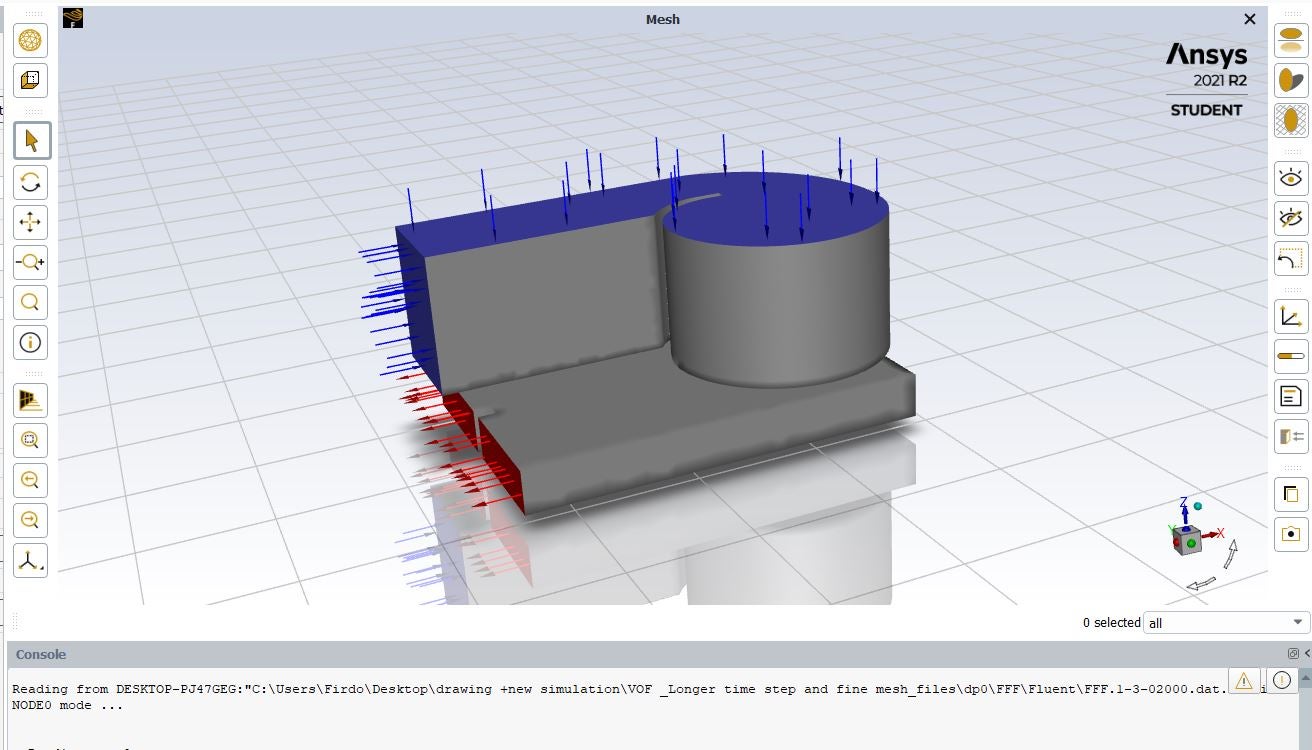
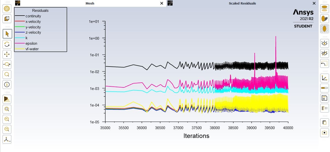
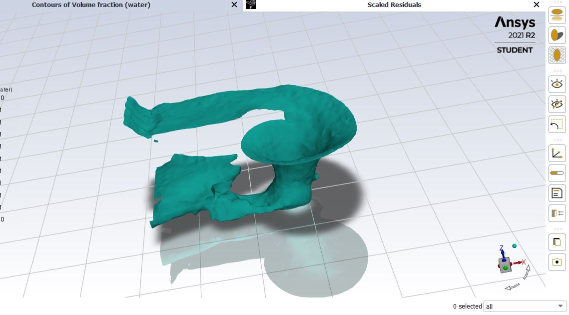
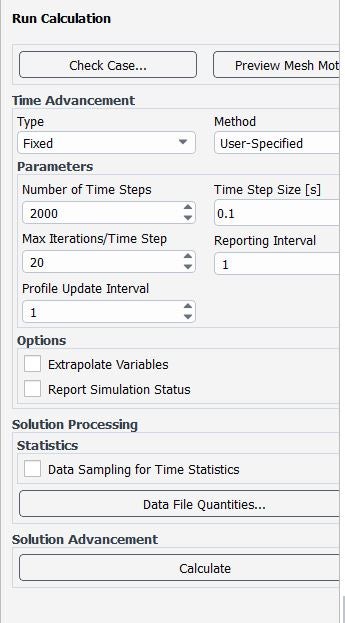
SubscriberI am modeling vortex formation and trying to study the vortex characteristics. I used mass flow rate as inlet BC, pressure inlet as top surface Bc and pressure outlet at the outlet. The gauge pressure in both case is zero (Is this okay ?). I run the simulation and the results I have attached. I wanted to know how can I know now that my simulation has reached the steady state ? How can I know whether my solution has converged or not based on residual ? Also I have used 0.1 s as my time step size and number of time steps 2000. How long should I run simulation and how can I know how long should it be run to reach steady state ?
December 23, 2021 at 3:47 pmRob
Forum ModeratorI'd possibly use a symmetry plane on the top as there shouldn't be any/much flow that matters. Equally pressure is fine. Convergence in these cases is harder to judge. Monitors of liquid mass are often useful. What isn't clear is whether each time step is converging, if it's not you may want to decrease the time step.
December 23, 2021 at 4:38 pmsailaja
SubscriberThank you for the reply.
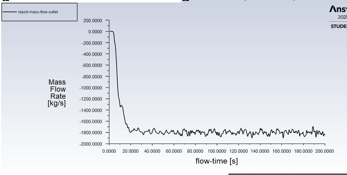
yes I have monitored the mass flow at outlet, the graph and report is shown here below. What I found is my mass flow at outlet is also fluctuating. MY inflow rate is 1800 kg/s but my out flow is fluctuating sometime its more than this and sometime its lower. I didn't understand why is this . Any suggestion for the solution to be converged in this case ?
December 24, 2021 at 10:53 amRob
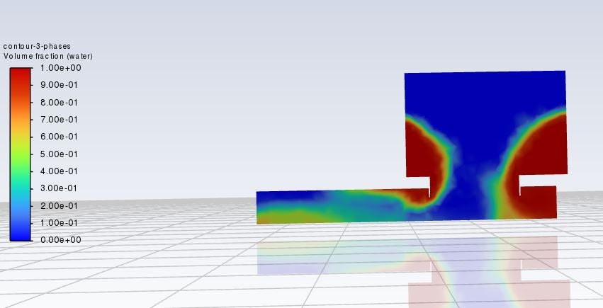
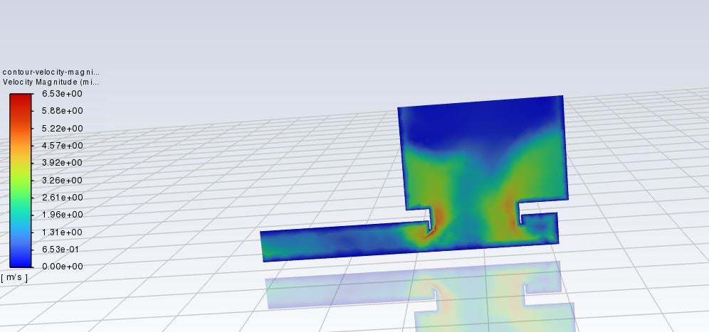
Forum ModeratorYou're modelling a vortex chamber: save an image of the free surface coloured by vertical position over a few hundred/thousand time steps and tell me what's happening. Assuming you are saving the data (and not just plotting) what is the mean flow from 120-200s?
December 26, 2021 at 5:06 pmsailaja
Subscriberhere is the report in which I have used 0.1 s time step size and number of time step to be 2000. The average value is 1801.1 kg/s. The values are in negative . what is the reason for negative value. Is it because of origin/coordinate of the geometry ? The picture are attached below.
Thank you in advance.
December 27, 2021 at 4:11 pmsailaja
SubscriberIn the residual plot above it is also noticed that, it is oscillating all the time. It means it is not converged ? I have changed the time step to 0.01 in next simulation , in that case also the graph is oscillating all the time. The setup of the simulation is as follow:
VOF model
K-epsilon (RNG)
Boundary condition: mass flow inlet (at inlet), pressure inlet (at free surface), pressure outlet (at outlet) -all the pressure BC are set at gauge pressure 0.
initialization from inlet with X-velocity 0.83 m/s
run calculation: time step size 0.01 s; number of time step 5000 and maximum iteration 20 (I am having problem to get converged solution. Might be there are something I am doing wrong while setting up the model. I am stuck at this point. Can you please suggest me the solution for this problem.)
December 28, 2021 at 4:08 pmRob
Forum ModeratorCheck the mesh resolution, and also the outlet condition: should there be a height of liquid in the outlet?
December 28, 2021 at 6:41 pmsailaja
SubscriberThank you for the reply.
I haven't considered the height of liquid at outlet. Should I assign the outlet water depth? I am doing VOF but not the open channel modelling. For now, its just outlet pressure at 0 gauge pressure I have assigned.
Also, when I see the simulation running, it is telling that reversed flow at the pressure inlet(top surface) and the pressure outlet(at bottom outlet). what does this mean ? Does this has impact on the getting residual plot oscillating every time? If so, how can I eliminate it ?
what is the meaning of residual and what message residual plot is trying to convey ? Does residual plot has to be always descending smooth curve ?
when we click run calculation, under time advancement , it has two option adaptive and fixed time advancement option ? what are the difference between this two option ? Which method would be better for faster convergence.
Thank you in advance
December 28, 2021 at 6:54 pmsailaja
SubscriberYou have asked me about mesh resolution, the mesh resolution value is 2 and I have used tetrahedron mesh.
what must be the mesh resolution value ? what I have noticed is when I choose "yes" in mesh adaptive option then only I can read the resolution of my mesh. So what is the difference in selecting yes or no ? what it does when we select yes?
December 31, 2021 at 12:43 pmRob
Forum ModeratorMesh resolution is relative to the domain. So 2mm could be very fine (100m domain) or very coarse (5mm domain). What you're looking for is to have enough cells to resolve the flow field and gradients.
Residual plots drop as per the tutorials if the solution converges, and give a periodic spike pattern in transient - have a look at the tutorials in the Help section. In your case it's suggesting the solution isn't stable, and probably ought to be run in transient.
The outlet condition could be critical here. If it's wrong then the water is falling out of the domain where in reality the outflow may be nearly full or some other level. I can't advise on that, other than to suggest checking what the experiment/paper did.
Viewing 11 reply threads- The topic ‘differences in pressure and Symmetry Bc’ is closed to new replies.
Innovation SpaceTrending discussionsTop Contributors-
4663
-
1545
-
1386
-
1230
-
1021
Top Rated Tags© 2025 Copyright ANSYS, Inc. All rights reserved.
Ansys does not support the usage of unauthorized Ansys software. Please visit www.ansys.com to obtain an official distribution.
-


Ansys Assistant

Welcome to Ansys Assistant!
An AI-based virtual assistant for active Ansys Academic Customers. Please login using your university issued email address.
Hey there, you are quite inquisitive! You have hit your hourly question limit. Please retry after '10' minutes. For questions, please reach out to ansyslearn@ansys.com.
RETRY


