TAGGED: transient
-
-
July 15, 2024 at 9:16 am
-
July 15, 2024 at 9:21 am
Serdar KALAY
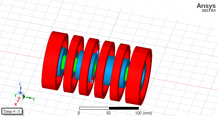
SubscriberI use transient solver type. blue and red coils are drive coils green coils are recieve coils. All the coils which are in the same colour are connected in series.6 red and blue coils and 4 green coils exist. I created 6 coil terminals for red coils and group them under a winding_red and create 6 coil terminals for the blu and group them under winding_blue. these two winding are in current type and have a sinusoidal current. drive coils create a magnetic field and therefore induce a voltage across green coils.Later I will put material (phantom ) inside the fourth green coil which will induce a voltage across the fourth green coil. In order just to see the induced voltage due to the material ı need to find a way so that induced voltage across the green coils as a result of magnetic field created by drive coils sum up to zero. Otherwise ı can’t see the induced voltage as a result of material since it is very small compare to the induced voltage created by drive coils. I first used polygon helixes since my system is symmetric according to zx plane ı chose recieve1 and recieve3 to turn right , recieve2 and recieve4 to turn left and this did the job but ı need to make them cyclindirical and don't know how to achieve same goal. I tried this: create winding for each recieve coil as win_recieve1,win_recieve2,win_recieve3,win_recieve4 chose their type as external, create an external circuit and connect every winding in series and add a 1Mohm resistance in series(did not put any source). After running the simulation ı created an output variable as InducedVoltage(win_recieve1)+InducedVoltage(win_recieve3)-InducedVoltage(win_recieve2)-InducedVoltage(win_recieve4) and InducedVoltage(win_recieve1)+InducedVoltage(win_recieve3). the second output variable is for control purposes. theoratically the time plot of first output variable must be 0 but ı get 7.5vpp and second output variable gives me 600vpp. isn't my logic corret , how can I achieve my goal(making the sum of induced voltage across recieve coils zero).I also did not understand the purpose of the resistance in the external circuit when unless ı add a resistance ı got an error, don't windings have internal resistance?
-
August 2, 2024 at 2:59 pm
HDLI
Ansys EmployeeHello Serdar,
I think the red coils and blue coils have entered current, and then the green coils will generate induced voltage, is it correct? Could you show the blue coils and green coils?
When you define coil terminal, the coil terminal's direction is voltage or current reference positve direction. You can use current of 0 or big resistance in external circuit to present open circuit.
When the coils are symmetry, the sum of the green coils may have 0 voltage as what you did. However, it seems that the blue coils are not symmetry.
To get what you expect, you have to design perfect turns for each coil after comparing induced volatge for each green coil.
HDLI
-
- The topic ‘determining turn directions in cylindirical coil:clkwise-counterclkwise’ is closed to new replies.


-
4904
-
1588
-
1386
-
1242
-
1021

© 2026 Copyright ANSYS, Inc. All rights reserved.


