
-
-
February 23, 2022 at 6:43 am
WolfgangNeil
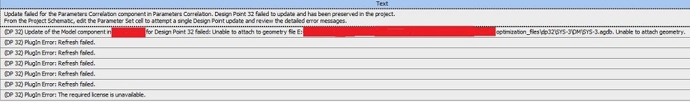
SubscriberI'm facing errors (image below) while updating certain design points using both Parameters Correlation and RSO within the Design Exploration toolbox.
February 23, 2022 at 11:31 amRob
Forum ModeratorWe're not permitted to open attachments, so please have another try.
If it's only certain design points, try and do the update manually. Typically errors occur when geometry gets twisted/changes topology (ie bits get chopped off) or the mesher can't cope with the new shape based on the previous settings.
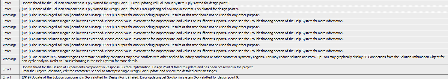
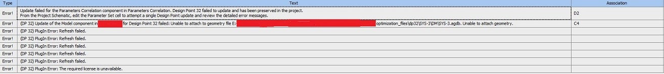
February 23, 2022 at 12:43 pmSubscriberThe screenshot for the error messages:-
 I've tried to insert the failing iterations of the DOE as design points in Parameter Set and tried to update locally but the same issue persists.
Can you please help me out?
February 23, 2022 at 1:58 pmForum ModeratorWhat's different about the geometry?
February 23, 2022 at 2:44 pmSubscriberI've modelled a cuboidal geometry in DM. For the DOE, the length, width and height are the input parameters.
February 23, 2022 at 3:09 pmForum ModeratorWhat dimensions are in the failed case, and what mesh settings did you use?
February 23, 2022 at 7:42 pmSubscriberI've created a new WB file with the same geometry. Right now I'm not getting any errors with geometry file attachment as per the screenshot I had shared earlier.
However, my observations are while performing the DOEs: -
1) For allowed value as "Any" for input parameters, the DOE is completed unhindered.
2) For allowed value as "Manufacturable" for input parameters, upon defining the distinct values, I'm getting an error for one DP for CCD type due to an un-converged solution.
Dimensions for failed DP: 793.5 x 345 x 1449 mm
 Further, I've tried to solve the DP separately by importing this DP into the parameter set. However, it failed to solve.
# Mesh setting: Linear element order with sizing (hard behaviour) and multi-zone method.
February 24, 2022 at 9:24 amForum ModeratorHard sizing and geometry parameters can be a problem if the geometry change breaks the sizing or forces a poor mesh. I'm not sure what a "linear element order" is, unless it's a Mechanical term? will know if it is - I drive Fluent CFD.
February 24, 2022 at 9:33 amSubscriberI'll try with some changes to the meshing.
In Mechanical, mesh elements can be created without mid-side nodes (linear element, Hex8) or with mid-side nodes (quadratic element, Hex20).
February 24, 2022 at 9:40 amForum ModeratorThanks for explaining. I knew about the mid-side nodes but not what the "normal" cells were called. In CFD we use more maths and just the Hex8, Tet4 and Poly"n" cells.
Viewing 9 reply threads- The topic ‘Design point update failure while using Design Exploration’ is closed to new replies.
Ansys Innovation Space Trending discussions
 Top Contributors
-
peteroznewman
 3832
3832 -
scabo
 1414
1414 -
Dennis Chen
 1193
1193 -
javat33489
 1100
1100 -
Shyam Prasad V Atri
1015
Top Rated Tags
© 2025 Copyright ANSYS, Inc. All rights reserved.
Ansys does not support the usage of unauthorized Ansys software. Please visit www.ansys.com to obtain an official distribution.
-


The Ansys Learning Forum is a public forum. You are prohibited from providing (i) information that is confidential to You, your employer, or any third party, (ii) Personal Data or individually identifiable health information, (iii) any information that is U.S. Government Classified, Controlled Unclassified Information, International Traffic in Arms Regulators (ITAR) or Export Administration Regulators (EAR) controlled or otherwise have been determined by the United States Government or by a foreign government to require protection against unauthorized disclosure for reasons of national security, or (iv) topics or information restricted by the People's Republic of China data protection and privacy laws.


