Fluids

Fluids

Topics related to Fluent, CFX, Turbogrid and more.

Design Modeler for Fluid Simulaton

    • Anthony Bowers
      Subscriber

      Hi all, I am working on a single-phase flow conditioner simulation. I want to create a good mesh of the part below. I have imprinted the faces of the flow conditioner holes onto the consecutive parts which allow me to name that surface as a wall ( As shown in the green) . I want the holes , that i imprinted, to then be removed or be ignored by the mesh... my goal is to have a mesh as shown below. As you can see the faces of the flow conditioner holes are still there but the mesh ignores the edges

    • Keyur Kanade
      Ansys Employee

      Can you please elaborate more. The green face you showed in the image is very easy to mesh for Mesher and it should not ignore edges of this face. Did you give Named Selection? Please go through help manual for more details 

      Please check following videos

      Ansys Meshing Sizing:
      https://www.youtube.com/watch?v=w4q6q8nKF3U

      DM Share topology:
      https://www.youtube.com/watch?v=IO4ZtwZdD2I

      Ansys Meshing: Meshing Methods:
      https://www.youtube.com/watch?v=nEOC8rDnnRo

      Ansys Meshing: Inflation:
      https://www.youtube.com/watch?v=lrEHXizrhC0

      Regards,

      Keyur

      How to access Ansys Online Help Document

      Guidelines on the Student Community

      Fluids Engineering Courses | Ansys Innovation Courses


    • NickFL
      Subscriber
      It looks like you are on the right track. The green face may have some trouble because the outer circles are very close perimeter of the green faces. This is due to the round on the lower "body". If I was doing the simulation I would remove this round unless you have deemed this a critical area. The elements in that region could become highly skewed.
    • Anthony Bowers
      Subscriber

      This is the mesh I am getting and I do not like the inner holes mesh. 

      • NickFL
        Subscriber

        Why do you not like the mesh that is there? What jumps out at me is that there is no inflation layer which is necessary to capture the sharp gradients within the boundary layer. Also you have a large jump in mesh size from the hex to the tets. You may want to apply some bias to the hex elements so there isn't a big jump. Do you want a conformal mesh between the two mesh types?

        Based upon your inquiry I expect you (or your professor) would like hex elements through these tubes. Hex elements will generally require less number of cells and be faster and more accurate for the same number of tet cells. Yes the body is simple enough that you could create a fully hex mesh for it. But it may take you 8 hours to decompose and get the mesh that you want. If you compare this to a tet mesh it may save you 8 hours (likely less) of compute time. But whose time is more valuable, yours or the computer?

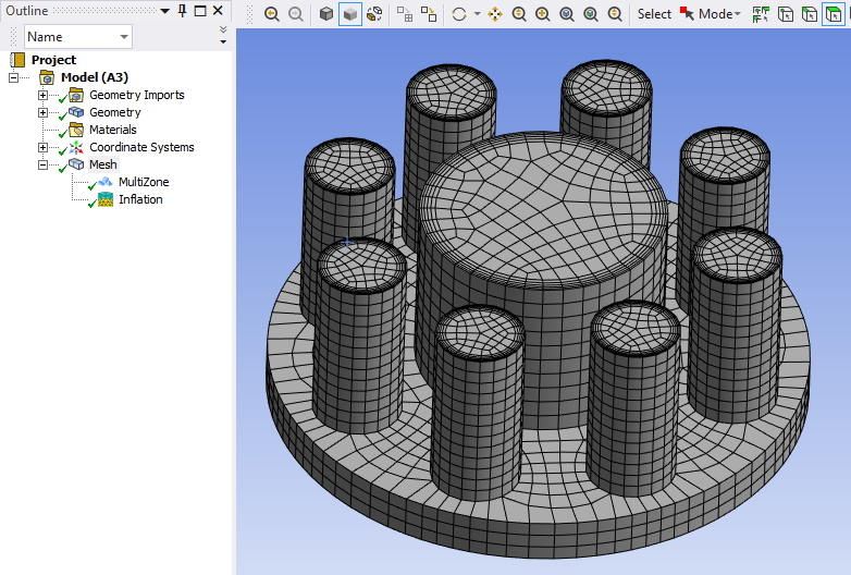
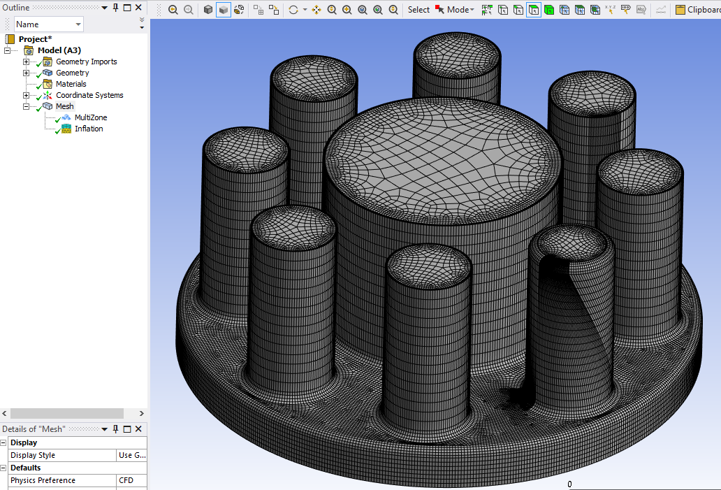
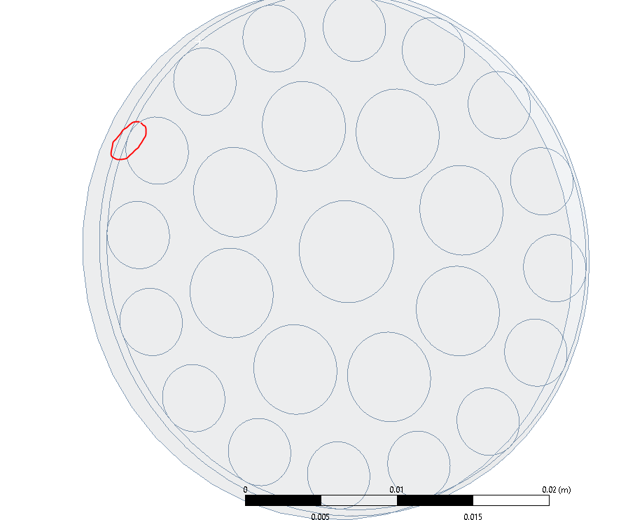
        I said that it would be possible to create a pure hex mesh, so how would you go about it? The first thing I would do is to remove the rounds as it looks like you only have one element through it anyways. This will help the mesher (and yourself) a lot. Then in ANSYS meshing you can use the multizone method to create a pure hex mesh. Compare the two pictures below. This is for without (upper) and with (lower) rounds. Due to the size of the round the mesh size is shrunk and the result is a huge number of elements (500000+ vs 23000). Also the lower image shows the mesh has some difficulty with the blocking on the several of the tubes and thus would require some babysitting.


    • Rob
      Forum Moderator

      Thanks Nick. I know you know what you're doing, but a comment for the OP to think about.  For a good mesh you must also consider that the cell resolution and growth are suitable for flow separation. A pure hex mesh in the above may be overly refined in the far field if you resolve the separation or too coarse in the separation region if you mesh for the far field. 

      Or look at Fluent Meshing and use polyhedral elements. Most of the benefits of hex with most of the benefits of tet mesh. Having historically decomposed for pure block hex because I had to I'm far more likely to take the "easy" option now I can. 

      • NickFL
        Subscriber

        Rob wrote:

        Thanks Nick. I know you know what you're doing, ...

        I am glad one of us thinks that???? I should have stated that neither of those meshes are adequate, but wanted to show the influence of the rounds and the power of the MultiZone method.

        • Rob
          Forum Moderator

          No further comment.... ;)   

    • Anthony Bowers
      Subscriber

      This al all very helpful thank you. I applied some advice and it partially worked. I was able to he get hexidomanint cells for the individual Flow conditoenr holes, but now the other section is giving me issue.  What do you guys suggest for meshing this part? As you can see by the red circle there is a very very small gap between this edge and the flow conditoner edge.. 


    • Anthony Bowers
      Subscriber

      How do you suppose the author acheived this mesh ?

    • Rob
      Forum Moderator

      Hard to tell from the image, but my guess is it's a hex block mesh, so possibly ICEM Hexa and an excessively large amount of time doing decomposition. There's a reason CFD solvers moved from i j k block meshes to the fully unstructured codes of today. 

      Re the gap - I'd remove the chamfer as Nick suggests or look into pinch control (Ansys Meshing). 

    • Anthony Bowers
      Subscriber

      Re the Gap- This geometry was provided by a company who designs FC ( Flow conditioners). Since it is a small chamfer I can assume little effects on the simulation?

    • Rob
      Forum Moderator

      I'll leave Nick to comment on omitting geometry. Rough rule of thumb, unless you plan on putting 3+ cells into a gap/feature it's probably safe to omit it. However, you're the one who has to defend any modelling assumptions to your Prof. 

Viewing 9 reply threads
  • The topic ‘Design Modeler for Fluid Simulaton’ is closed to new replies.