-
-
September 22, 2018 at 4:08 pm
Samar
SubscriberHi everyone,
I am working on Transient Thermal module; using Input parameters (Temp.) and (Internal Heat Generation). My main problem is that the output temperature curve increases gradually till reaching the max. temp. then becomes constant even if i increased the "End Step time"; My expected result is that the Temp. increases gradually till max. value then decreases again.
So any help to fix this issue ?? -
September 22, 2018 at 5:51 pm
peteroznewman
SubscriberHi Samar,
Can you show the Boundary Conditions for your Model and the time variation on each of them?
Can you show the solution for a much longer time?
Regards,
Peter
-
September 22, 2018 at 8:19 pm
Samar
SubscriberFor now am working on a sample model (2D rectangular Sheet with a circle in it) to check workflow on it before applying it on my real model.
My Boundary conditions are:
1- Temperature on the rectangular sheet = 37C. (There is no difference if i apply the temp. on 4 edges or on the sheet itself).
2- Internal Heat Generation on the Circle = 371 W/mm3.
-
September 23, 2018 at 1:29 am
-
September 23, 2018 at 10:42 pm
Samar
SubscriberI have 2 questions:
1- When i apply the temp. on edges, the temp. curve didn't decrease (I was applying a constant value of temp. = 37 on the 4 edges) is that the reason the output temp curve increases gradually then becomes constant once reach it's max. temp.?
2- Why did you apply "Convection" on 1 edge ?
-
September 23, 2018 at 11:23 pm
peteroznewman
Subscriber1. When you apply a temperature Boundary Condition to the edges of a block of material, that is a fixed value that is enforced during the solution for all time. If you start with an object at 22 C at time = 0 and have four edges at 37 C and an internal heat generation, the block of material is only going to heat up. The maximum temperature in the block is only going to increase and never decrease. Why do you think it would decrease?
2. I put Convection on one edge to demonstrate a common Boundary Condition.
-
September 23, 2018 at 11:45 pm
Samar
Subscriber1- I thought that temp. would decrease as after 'X' period of time, there will no source of heat, so temp will decrease to the default (Temp. of boundary condition); Is that a wrong way of thinking ?
2- I tried my 2D model with the same input parameters as yours, but didn't get the same distribution for temp. even with changing materials
3- Am sorry, i still don't understand the necessity of "Convection"; is it important to be inserted for most of the transient thermal analysis ? or it's just for clarification (explanation) for me
-
September 24, 2018 at 12:43 am
peteroznewman
SubscriberDid you set Share Topology to Share so that the two bodies share nodes at the circular edge?
When you do that, the mesh aligns.
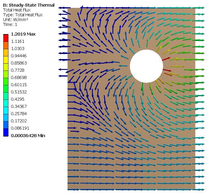
If you have a left edge Temperature Boundary condition of 100 C, an internal heat generation, and a convection BC on the right edge, then heat will flow out of the left edge with the 100 C edge to maintain the 100 C. You can see this if you plot Heat Flux. You can plot arrows of a fixed length to show direction, or you can plot the arrow length to be proportional to the magnitude of the heat flux so a point where the heat flux is large gets a long arrow and a point where the heat flux is small gets a short arrow. The plots below have fixed length arrows.
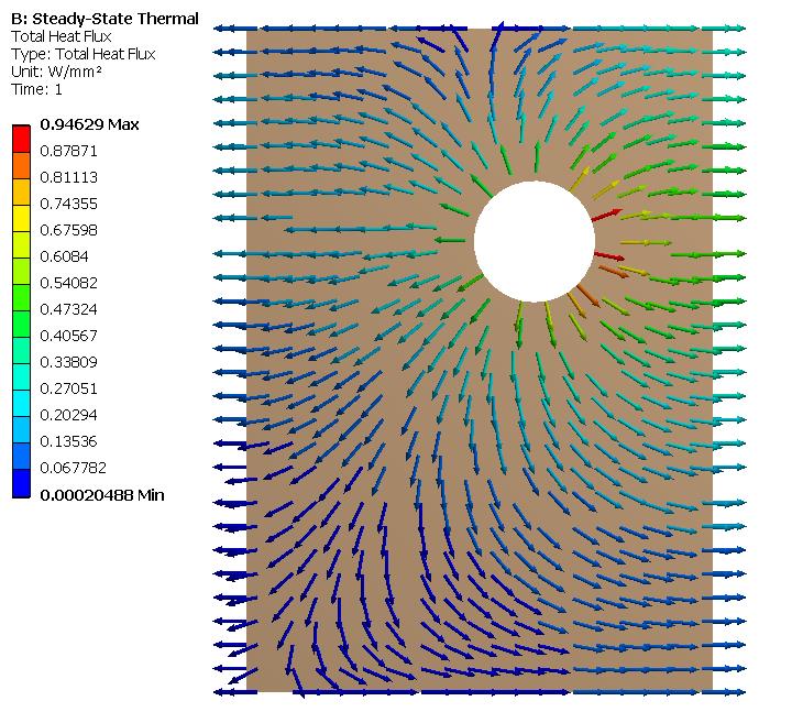
If you make the left edge Temperature BC 500 C then for the SS solution, the heat will flow in from the left edge.
And if you make the left edge Temperature BC 300 C, then the SS solution is the the heat flow changes direction from out to in on the left edge as you look from the top to the bottom.
The above were all Steady State Thermal analysis results. You should look at a Steady State result before you develop Transient models. For one thing, they solve a lot faster. Why do you think the Transient solution is important?
3. Convection is a common BC because solid objects are usually touching some fluid, often air, that is at some bulk temperature, say room temperature of 22 C. Heat can flow out of a hot solid and into the room air by means of convection. Or heat can flow into a cold solid from the warmer room air by means of convection. The convection film coefficient defines the heat flux as a function of the temperature difference between the solid and the air.
-
September 24, 2018 at 2:01 am
Samar
Subscriberokay, i tried the same example as yours on a steady state module after checking the (Share Topology) and update it to be: Edge joints. [It was automatically set to: Automatic]. but unfortunately i didn't get the same distribution as yours
don't know whats the problem with me.
And about "Why i need to solve transient thermal module?"; here is the Ans.:
Am working on a part in human body that it's temp. increases after specific period of time as result of being supposed to a light source that heats this part. So for the sample sheet model; am assuming that the rectangular sheet is the "Fats" in human body and the circle is a "Tumor".
My Input parameters and boundary conditions are a map for internal heat generation values and temp. for each body.
-
September 24, 2018 at 4:03 am
peteroznewman
SubscriberSamar,
What version of ANSYS are you using?
Which Geometry editor are you using: DesignModeler or SpaceClaim? I think you are using DesignModeler, since you mentioned Share Topology was set to Automatic. Unfortunately, I was showing you a screen snapshot from SpaceClaim.
If you want to Attach a Workbench Project Archive .wbpz file to your reply after you post it, I can open it and take a look at what is in your model.
It would help me to help you if you can share more details of this thermal model you want to build. You can put any type of file such as *.ppt into a *.zip file and you can Attach a zip file to your posts here also. Heating of material using light can be done in ANSYS using Radiation loads, but those are for opaque objects where the energy is absorbed at a surface and then conducted into the material. Tissue such as skin, fat, muscle and tumor is translucent and light enters the material where a volumetric conversion of light energy into thermal energy occurs. I don't think ANSYS can model that, but I know about ray tracing software that can.
Regards,
Peter
-
September 25, 2018 at 2:41 am
Samar
SubscriberI mentioned everything in the attached file, If you don't mind please check it. and as well add my project on (Workbench Project Archive).
Thank you for sharing the guidelines link for me.
I can't upload the Zip file, is that bec. the discussion is checked as solved ?
-
September 25, 2018 at 3:01 am
peteroznewman
SubscriberHow big is the zip file? It has to be < 120 MB. If it is larger then you can post a link to the zip file on your Google Drive.
-
September 25, 2018 at 3:05 am
Samar
SubscriberNo it's a very little one (3 MB) zip file
-
September 25, 2018 at 3:41 am
-
September 25, 2018 at 8:11 am
Samar
SubscriberI exactly did what is in the above steps, and it's not upload even from different browser, although I have attached files before by the same way !
I also try to attach it with the project's file, but it didn't work :S
Update: I tried diff. extensions and finally it accepts the .pdf and file successfully attached.
-
September 25, 2018 at 12:05 pm
peteroznewman
SubscriberThere is a simpler way to make the hole in the rectangle, just draw the circle in the rectangle on that sketch, then when you convert the sketch to a surface, there will be a hole in it. No need to use a Boolean.
There is a better way to Share Topology in DesignModeler. After you create the second body, the circle, you pick the two bodies in the Outline, then right click and Form New Part. Then you will go from 2 Parts, 2 Bodies to 1 Part, 2 Bodies. Then the Share Topology, Automatic setting that is the default will create shared nodes on the circle in meshing.
Did you try creating a .wbpz file using File > Archive? You can't attach a .wbpj file extension because that file alone is not useful.
Yes, the triangular pulse was essential to get the temperature to build up and die down. However, you have put in a FWHM pulse width of 1 second, while the paper you show says to use 1.25 ns. The reason you can have such a high heat generation value is because the time it is on is so very, very short.
There is no need to simulate any time before the triangular waveform starts. Nothing is happening then. You want to solve for some good long time after the waveform has passed.
Regards,
Peter
-
September 25, 2018 at 6:33 pm
peteroznewman
SubscriberSamar,
I found your post in the wrong discussion. Please delete it from there and post it here, if it is still relevant.
Regards,
Peter
-
September 25, 2018 at 11:53 pm
Samar
SubscriberFirst of all Thank you very much for your time and effort and Sorry for posting on a wrong discussion.
2D Project (Rectangular Sheet) solved in Transient Thermal Module.
-> I have increased the number of steps and also try to change in the value of internal of heat generation and check the difference in max. value of temp.
-
September 26, 2018 at 4:03 am
peteroznewman
SubscriberSamar,
It seems you have put the 37 C Temperature condition on the circle around the tumor. That seems wrong. I think you only want that on the outside edge, not on the circle as well.
Regards,
Peter
-
September 26, 2018 at 8:16 am
Samar
SubscriberWhen i didn't put temp. on the edges of circle; the output temp. gives temp. in -ve values that min. is not equal = 37C ! is that accepted ?
And from the paper am following, it mentioned that initial temp. applied on all nodes (either fats and tumor) that's why i applied it on the edge of circle.
-
September 26, 2018 at 7:45 pm
peteroznewman
SubscriberThe Temperature BC applies for all time. The Initial Temperature is a separate setting.
-
September 28, 2018 at 11:06 pm
-
June 1, 2020 at 12:42 am
peteroznewman
Subscribersunil.voleti, please copy your text and paste it into a New Discussion in the Thermodynamics category, then delete the post above.
You can include a link to this discussion for reference.
-
June 9, 2020 at 2:41 pm
sunil.voleti
Subscriberhello peter,
i created new discussion and please reply me in this new discussion.
-
- The topic ‘Defining Time for Transient Thermal Module’ is closed to new replies.
-
4893
-
1587
-
1386
-
1242
-
1021
© 2026 Copyright ANSYS, Inc. All rights reserved.


