-
-
July 30, 2018 at 11:42 am
jonsys
SubscriberThe arched body shown in Fig 1, is supposed to act as a mold for the flat pane. I don't want the mold to be deformed, I just want the loaded pane to follow it's geometry. Therefore, for the mold, I defined the Stiffness Behavior (Mechanical > Geometry > Definition) as Rigid.
When the mesh is generated, only the upper surface of the mold seems to be meshed (as in Fig).
- Is the definition of the mold as rigid done properly?
- Since it is defined as Rigid, does it matter what material do I assign at that solid element?
- Why is the upper surface of the mold meshed?
- Do I need to define Contact between these two bodies?
-
July 30, 2018 at 12:34 pm
peteroznewman
SubscriberHi Jon,
- Is the definition of the mold as rigid done properly? Yes.
- Since it is defined as Rigid, does it matter what material do I assign at that solid element? No.
- Why is the upper surface of the mold meshed? That is where you defined contact.
- Do I need to define Contact between these two bodies? Yes, between the two faces.
There is one difference when defining contact with a rigid body, the rigid body must be the Target side of the contact.
Regards,
Peter -
July 30, 2018 at 1:15 pm
jonsys
SubscriberHello Peter,
thank you for the answer.
Do I need to define boundary conditions for the rigid body?
I don't have a lot of experience in ANSYS, therefore if you have any suggestions on how to define Contact (or which type), can you please let me know? Moreover, the lower face of the pane is a continuous one; should this face be split in two, one of those to be the same width as mould?
Regards,
Jon -
July 30, 2018 at 1:32 pm
peteroznewman
SubscriberHello Jon,
Mechanical doesn't allow Fixed Supports for rigid bodies. To fix the rigid body to ground, in the Connections folder insert a Fixed Joint.
It would be a bit more efficient solving if you split the face in two.
Try the default contact definition initially, but use a Contact Tool and Generate Initial Contact Status to ensure that the contact is initially closed before the analysis starts.
Is the pane a surface body assigned the thickness of the pane? That is what you want, not a solid body. A surface body will be meshed with shell elements that are very good at computing bending. A solid body needs many elements through the thickness to give good results for bending problems.
When you have a midsurface model, turn on shell thickness effect in the contact definition to handle the t/2 gap between the surface and the rigid body face.
Regards,
Peter
-
July 31, 2018 at 1:15 pm
jonsys
SubscriberHello Peter,
I split the face in two but I still got errors while running the file. Sometimes when the load is too big, the pane gets through the rigid body and that is not supposed to happen. I guess I am defining contact wrong. Some errors are shown below. If it is possible for you to take a look, can I upload the file?
Regarding to the pane: It is a solid body. Firstly I want to make it work with solid bodies (that how it is required), but once I make it work I will try shell elements as well for comparison.
-
July 31, 2018 at 1:30 pm
Sandeep Medikonda
Ansys EmployeeHello Jon,
Have you tried increasing the pinball radius? make it significantly bigger than what you are seeing in the Initial Contact Status. If that doesn't work, try adding a small damping factor, maybe start with 0.05 initially and increase as needed?
~Sandeep
-
July 31, 2018 at 2:20 pm
peteroznewman
SubscriberHello Jon,
There are some settings in the Contact Details window, such as Pinball Radius as Sandeep mentions, and also Trim Contact.
Create a Workbench Project Archive .wbpz file and use the Attach button after you post your reply. File size limit is 120 MB.
Use Mesh Controls to Sweep four SOLSH190 elements through the thickness of your pane. These have better accuracy in bending problems than the standard solid elements.
Regards,
Peter
-
August 1, 2018 at 9:39 am
jonsys
SubscriberHello Peter and Sandeep,
I tried to increase the pinball radius, but it results in a gap between pane and mould. I used the default contact type Bonded; could that be a reason?
attached is the project archive, thank you.
Thanks for SOLSH190 suggestion
Regards,
-
August 1, 2018 at 9:44 am
jonsys
SubscriberHello Sandeep,
how can I add a damping factor?
Regards,
-
August 1, 2018 at 3:13 pm
peteroznewman
SubscriberHello Jon,
ANSYS provides default values that are sometimes what you want, but in this case, that default choice is not what you want.
Change Bonded to Frictional in the Contact between the Glass face and the Rigid mold form.
Add a Contact Tool and Generate Initial Contact Status, you find there is a small gap.
Use Adjust to Touch in the Contact to close the gap.
Under Analysis Settings, you must set Large Deflection to On.
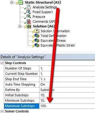
You also want to ramp up to the full load in 100 steps.
I went into DesignModeler and sliced all the bodies so that the meshing didn't complain about Sweep being applied to a pane that had two faces on one side and only one face on the other side, but it is still not accepting the Thin Sweep that assigns SOLSH190. The slice did not use the parameter, but it could later.
https://youtu.be/2SZ046GX6XE
The attached ANSYS 19.1 archive.
Regards,
Peter
-
August 2, 2018 at 1:48 pm
jonsys
SubscriberPeter,
this is amazing. thank you very much.
I use a 17.1 version of ANSYS; however I opened your attachment with the student version and implemented in 17.1 version (I decreased the load though).
From the changes that you made to make it work, there are a lot of things that I am not familiar with and I will need to look in the literature to deepen my understanding about them. I will also play a little with the parameters like radius of mould, time steps etc to see the effect. I might have again questions so I will ask them later.
However, I would like to know some things beforehand:
What is the purpose of the command NEQIT,60 you added at Static Structural.
Or should any contact options be changed in case I change the radius of the mold?
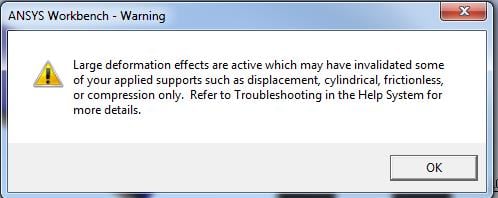
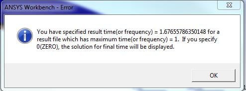
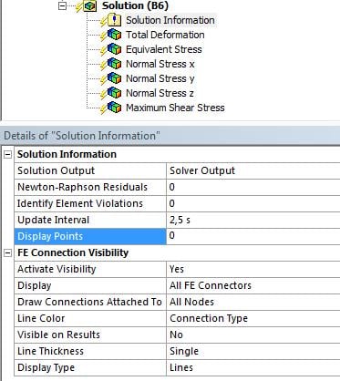
The solutions are not ticket, eventhough there is output for the substeps [Fig 1], and there are some errors and warnings.
These were not on your 19.1 version right?
Regards,
Jon
-
August 2, 2018 at 2:14 pm
Sandeep Medikonda
Ansys EmployeeJon,
You have one of those the results in there where the 'Display Time' is set to this specified time. So please go over them and change it to 0. This should eliminate this error.
~Sandeep
-
August 2, 2018 at 3:35 pm
peteroznewman
SubscriberJon,
The default behaviour of the Auto Time Stepping is to attempt to converge in no more than 26 iterations. In your model, it gets close to converging in 26 iterations, but hasn't quite got there and needs more iterations to converge. You can see that in the third and fourth substeps below. The NEQIT,60 gives the Auto Time Stepping algorithm a new limit of 60 iterations.
I got the same Warning about large deformation may have invalidated... After you check your results, you can ignore this warning.
Regards,
Peter
-
August 3, 2018 at 1:17 pm
-
August 3, 2018 at 1:20 pm
jonsys
SubscriberPeter,
so that means that a maximum of 60 iterations per substep is assigned?
Regards,
-
August 3, 2018 at 1:23 pm
-
August 3, 2018 at 2:09 pm
jonsys
SubscriberSandeep,
Display time was set to 0, but I guess the mistake was because the Initial substep was 100, Min Substep 10, Max Substep 100. I changed min Subst. to 10 and it is working. thank you
-
August 7, 2018 at 1:39 pm
jonsys
SubscriberHello Peter,
In case you have time, I would like some confirmation or suggestions.
So the Contact Tool is used to have take a look on the contact before analysis? Can I do a parametric study, changing the mold radius? - or do I have to generate Initial Contact eveytime before Solving, therefore this makes it impossible to do parametric study?
How is the pinball radius value is decided?
Regards,
Jon
-
August 7, 2018 at 1:54 pm
Sandeep Medikonda
Ansys EmployeeJon,
Regarding the pinball radius, here is an useful article on how it is determined.
With regards to parameterizing the pinball radius, theoretically, it can be done by using APDL command object but it could be an involved effort as you would iterate and change the radius using the RMOD command.
Regards,
Sandeep
-
August 7, 2018 at 2:57 pm
jonsys
SubscriberSandeep,
Thank you for the suggestion.
In the article is stated that anything outside the pinball radius (in Frictional Contact), is not checked by ansys whether the contact and target are in contact.
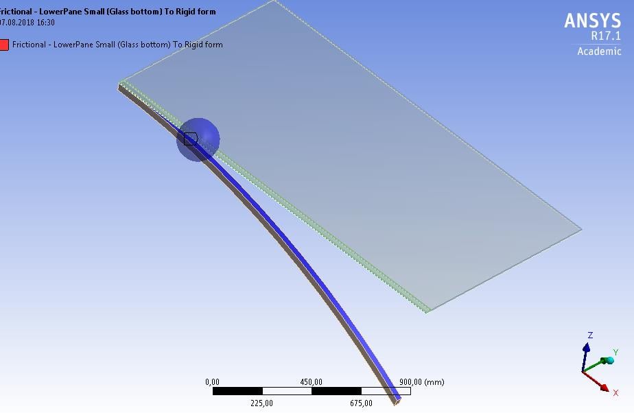
My pinball region of radius 100 is shown in the picture; however I can get information like (pressure, gap, sliding distance) for all regions of contact (eventhough they are outside the radius).
Moreover, I don't understand what (how) Initial Information of Contact Tool is used for further modification of contact.
Regards,
Jon
-
August 7, 2018 at 3:23 pm
Sandeep Medikonda
Ansys EmployeeJon,
The initial contact tool will just allow you to assess the initial contact conditions of your model and help make changes to your contact definitions. You ideally want to avoid open contacts.
The pinball region has little to do with you looking at contact pressure etc. Isn't this a post-processing result? Right click on the results and insert a post-processing contact tool. You can then right click again on it to insert various options as shown. These are automatically scoped to all the regions that were in contact during the simulation.
~Sandeep
-
August 7, 2018 at 3:39 pm
jonsys
SubscriberSandeep,
My point is: A majority part of my model [where I want contact] is outside that pinball radius (blue sphere on the pic) -> the article you sent me, says that outside this pinball region, elements will not be checked for contact -> and I am asking, if it is not checking, why do I get results (even for the part outside the blue sphere) on post-processing?
Regards,
-
August 7, 2018 at 4:39 pm
Sandeep Medikonda
Ansys EmployeeJon, The pinball is just an illustration at one point. There are pinballs at every node and once the bodies come closer, they will eventually fall into this zone.
The reason for having the pinball is in implicit, due to the bigger time increment there is a good chance for the bodies for a certain load and completely miss. So once both the contact side and the target side are in this region say for a node, the contact algorithm activates and will keep working behind the scenes to make sure that it is being enforced.
-
August 8, 2018 at 6:53 am
jonsys
SubscriberSandeep,
alright, now I see. Thank you very much
Regards,
-
November 14, 2023 at 2:56 pm
antony20me
Subscriberhi , i have a doubt regarding the explicit analysis of a vehicle rollcage in LS-DYNA. How to give fixed support boundary condition if my body is assigned as rigid , since in the first comments it has been told that for rigid body in mechanical..we can't assign fixed support as a boundary condition. And also in that comments it also mentioned that we can use fixed joints by inputing it in connection folder.But will it be okay to run the analysis and to get the right result if we didn't gave the fixed support to object which is to be hitted by a vehicle.
-
- The topic ‘Defining rigid body and contact’ is closed to new replies.


- LPBF Simulation of dissimilar materials in ANSYS mechanical (Thermal Transient)
- Real Life Example of a non-symmetric eigenvalue problem
- How can the results of Pressures and Motions for all elements be obtained?
- BackGround Color
- Contact stiffness too big
- Element Birth and Death
- Python-Script to Export all Children of a Solution Tree
- Which equations and in what form are valid for defining excitations?

-
4597
-
1495
-
1386
-
1209
-
1021

© 2025 Copyright ANSYS, Inc. All rights reserved.


