-
-
May 18, 2024 at 4:18 pm
chiheb ben abdallah
Subscriberhello,
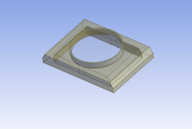
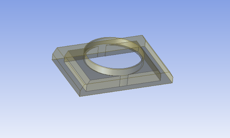
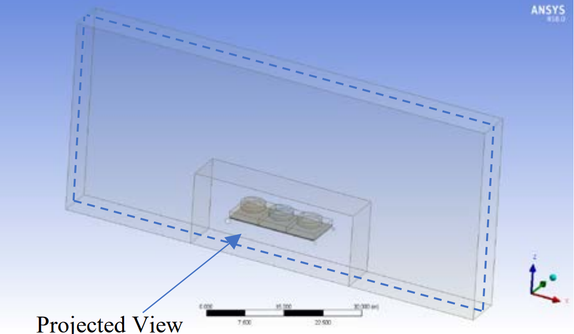
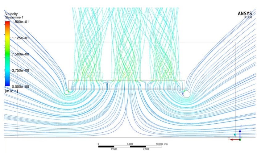
i want to simulate a phenomenon of hot air recirculation at the exhaust of an Air cooled heat exchanger where i want to simulate the air flow both through the exhaust and surrounding it.
i created a fluid domain by first creating 2 surfaces from the circular edge at the top and the recangular edge at the bottom then used a fill tool with the 2 surfaces and the solid geometry to create a fluid domain but it only simulates the results at the interior of the exhaust. i would like to use the rectangular surface as inlet the circular surface as outlet but i want the air flow to go through the exhaust and in a large zone surrounding it.
-
May 20, 2024 at 11:06 am
Rob
Forum ModeratorIf you want flow on both sides of the above object you'll need to create a volume for "outside" too.
-
May 20, 2024 at 12:53 pm
chiheb ben abdallah
SubscriberThank you Rob,
I'm having trouble defining the fluid domain to simulate the air flow initially going inside the exhaust then recirculating and moving around the exhaust and going back in the intake of the exhaust (rectangular surface) +I don't know how to define and modify or delete interiors, walls,inlets and outlets in solution mode can you help me with that
Thank you
-
-
May 20, 2024 at 1:26 pm
Rob
Forum ModeratorYou need to add volumes at the geometry stage. I suggest sketching (on paper) what you want to model, write on flow data etc. Only then open up the geometry/CAD tool to start work on the CFD project.
-
May 21, 2024 at 7:03 am
-
-
May 21, 2024 at 10:05 am
Rob
Forum ModeratorIt's been a while since I last modelled that sort of thing - there's an article where we modelled a dummy LNG plant to highlight some of the potential issues with the units.
You need to start with the basics, so have a look in Learning for the geometry, meshing and solver settings. Also have a think on how you want to handle the fan flow, HX units etc: have a look for
Hot Air Dispersion on an Air-Cooled Gas Liquefaction PlantHot Air Dispersion on an Air-Cooled Gas Liquefaction Plant Scandinavian Oil & Gas Magazine, No 3/4, pp69-71 · Jan 1, 2008-
May 28, 2024 at 9:19 am
chiheb ben abdallah
SubscriberHello Rob,
I have a question about the 3D Fan zone. What is the default geometry of a fan in Ansys fluent ( geometry and number of blades) what does inflection point mean?
Thank you
-
-
May 31, 2024 at 1:04 pm
Rob
Forum ModeratorI don't think there is a default geometry, it's a pressure jump boundary: note there are two fan options, one for a surface and another for a volume.
-
June 5, 2024 at 9:55 pm
chiheb ben abdallah
SubscriberHello Rob,
i have two questions : is it possible to define a profile of pressure or temperature at the interior of a fluid domain, if yes how can i do that? i defined profile for velocity and other quantities using udfs but i would like that the air pressure and temperature variate as function of altitude at the interior of domain
i tried setting 3D Fan zone in one of the fuid zones ( i set the fan origin coordinates at the center of exhaust, i set the fan axis parallel to the flow,the fan velocity and the pressure jump) when i press calculate, the fluent cell returns error folating point and immediately closes) what is the default geometry of the fan and how can i fix this problem?
i appreciate you helping me with this. thank you in advance.
-
-
July 3, 2024 at 9:02 am
Rob
Forum ModeratorAn interior is just a meshed surface in the model - you can monitor the flow on it, but that's it. If you want to suck flow out & blow it into the domain at pre-set rates you'll need (velocity) flow boundaries. Using paired boundaries so you suck in some kg/s and then return the same kg/s at a higher temperature is allowed, and Expressions will make this much easier than would be the case with UDFs.
-
July 3, 2024 at 9:07 am
Rob
Forum ModeratorAn interior is just a meshed surface in the model - you can monitor the flow on it, but that's it. If you want to suck flow out & blow it into the domain at pre-set rates you'll need (velocity) flow boundaries. Using paired boundaries so you suck in some kg/s and then return the same kg/s at a higher temperature is allowed, and Expressions will make this much easier than would be the case with UDFs.
-
- The topic ‘Defining fluid domain’ is closed to new replies.


-
5004
-
1681
-
1387
-
1248
-
1021

© 2026 Copyright ANSYS, Inc. All rights reserved.


