-
-
October 18, 2023 at 4:03 pm
-
October 18, 2023 at 9:19 pm
Federico
Ansys EmployeeHello,
I'm not sure I understand physically what you're trying to do. If your model is axissymmetric, then there cannot be a wall.
-
October 19, 2023 at 4:02 pm
zwong32
Subscriberessentially, I'm trying to model a hot rod inside the nozzle, but with an axis BC applied at the line of symmetry
I agree, you can't have a wall at the axis since that's physically impossible. But I need a heat column (via a wall or source) revolved around my axis. Does this make more sense?
-
October 19, 2023 at 7:08 pm
Federico
Ansys EmployeeRight, I understand better now. In that case, you might have to provide a thickness for your rod, make it a source, and identify the outer edge as your axis. You cannot assign any boundary conditions, thermal or other, to an axis.
-
October 19, 2023 at 7:15 pm
zwong32
SubscriberOk; one follow up question- I've specified the "hot" wall region as a "solid" zone, and everywhere else as the "fluid" zone. But I get the following error message:
Warning: materials in neighbor cell threads (2 and 6) of
interior zone 11 are of different types (aluminum and air).
Do you know what this is related to? I'm making my mesh via Pointwise instead of ANSYS' internal meshing tool
-
October 19, 2023 at 7:49 pm
zwong32
SubscriberI think I figured it out - but it's not the best solution. What are your thoughts on the following (thank you again so much):
Essentially, I had to go to Pointwise and specify both regions as a fluid. Then under internal BC's, set a fixed temperature value. I did this for a simple "flow in the box"; no slip condition on top wall, inlet velocity BC, pressure outlet BC, axis on the bottom wall and "side" walls. The temperature plot matches what I was expecting, but the velocity contour plot looks incorrect - i'd expect an even gradient near the "hot" fluid region:
*first image is a diagram of the mesh+BC; 2nd /3rd imags are contour plots
-
October 19, 2023 at 7:54 pm
Federico
Ansys EmployeeDoes this wall have a wall/shadow pair? This is required for heat transfer between different materials.
If you don't see this in your boundaries zones, try the following command in the TUI console:
define/boundary-conditions/modify-zones/slit-face-zone
then enter the Face ID of that boundary.
-
- The topic ‘
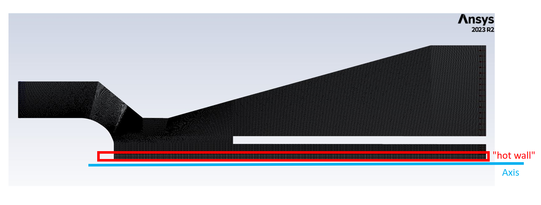
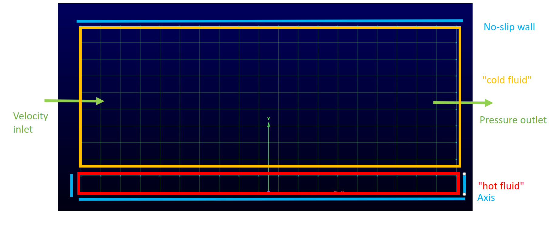
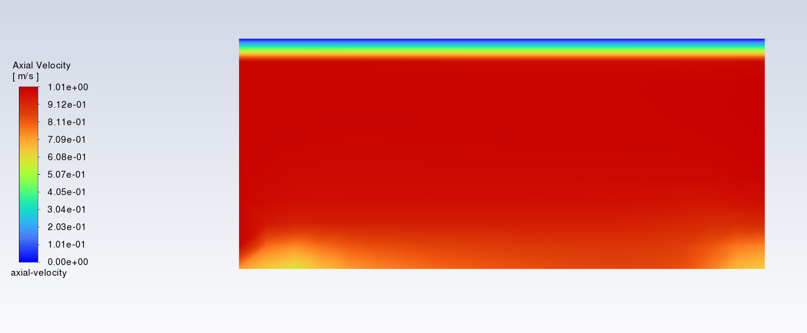
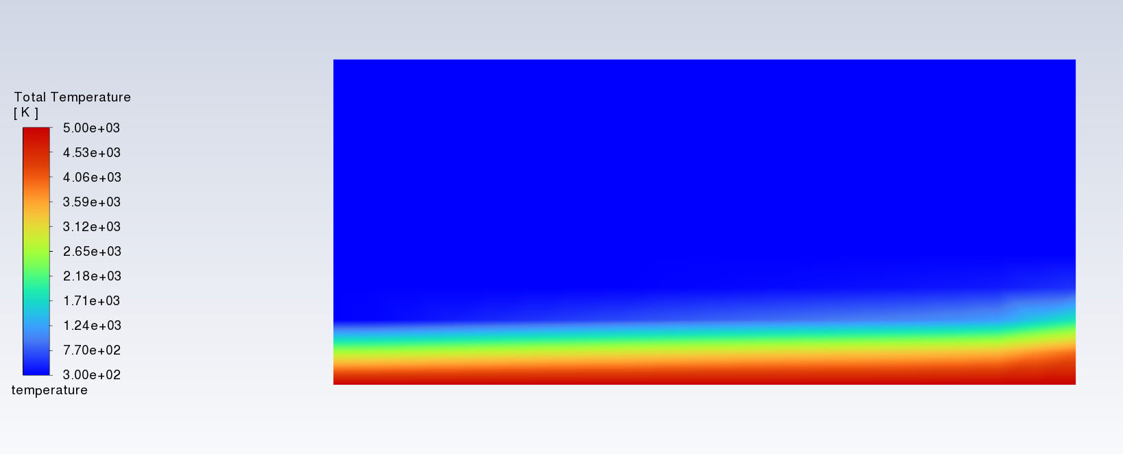
Defining an isothermal wall next with axis boundary condition’ is closed to new replies.
- air flow in and out of computer case
- Varying Bond model parameters to mimic soil particle cohesion/stiction
- Eroded Mass due to Erosion of Soil Particles by Fluids
- I am doing a corona simulation. But particles are not spreading.
- Centrifugal Fan Analysis for Determination of Characteristic Curve
- Guidance needed for Conjugate Heat Transfer Analysis for a 3s3p Li-ion Battery
- Issue to compile a UDF in ANSYS Fluent
- JACOBI Convergence Issue in ANSYS AQWA
- affinity not set
- Resuming SAG Mill Simulation with New Particle Batch in Rocky
-
4167
-
1487
-
1338
-
1188
-
1021
© 2025 Copyright ANSYS, Inc. All rights reserved.


