-
-
October 4, 2023 at 7:56 am
100041488
SubscriberHi all,
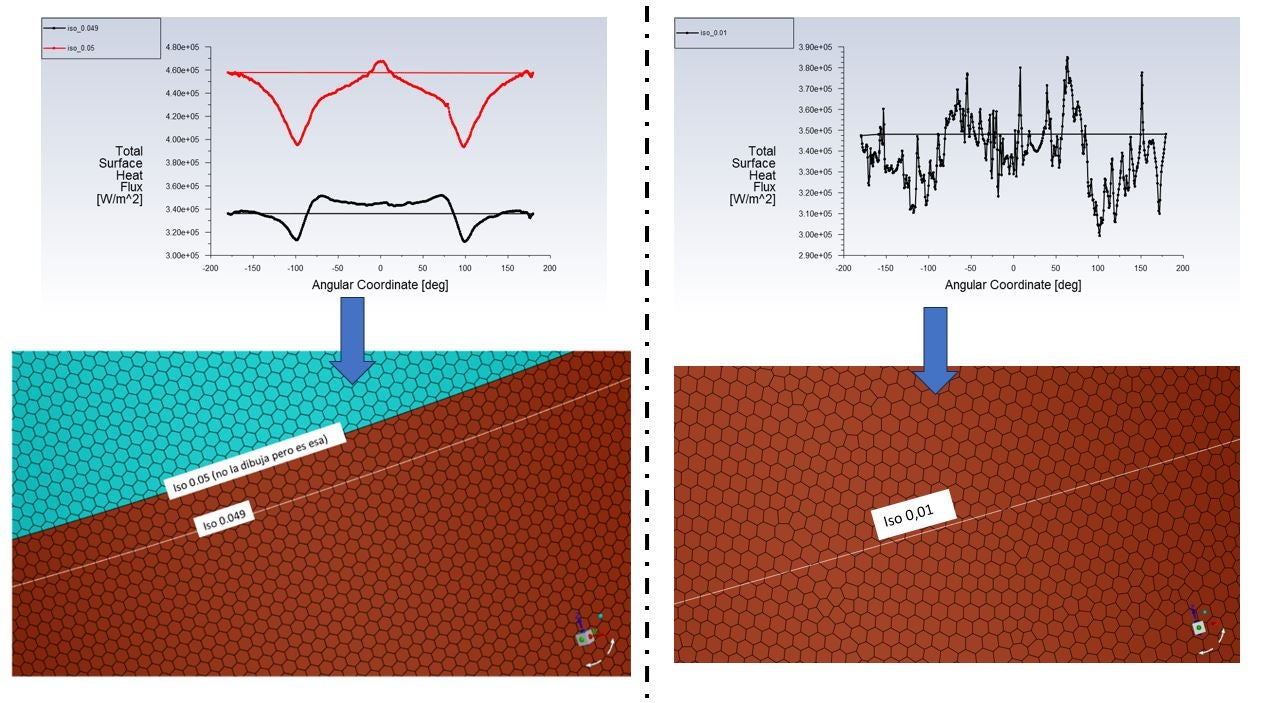
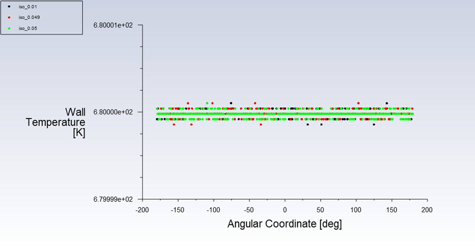
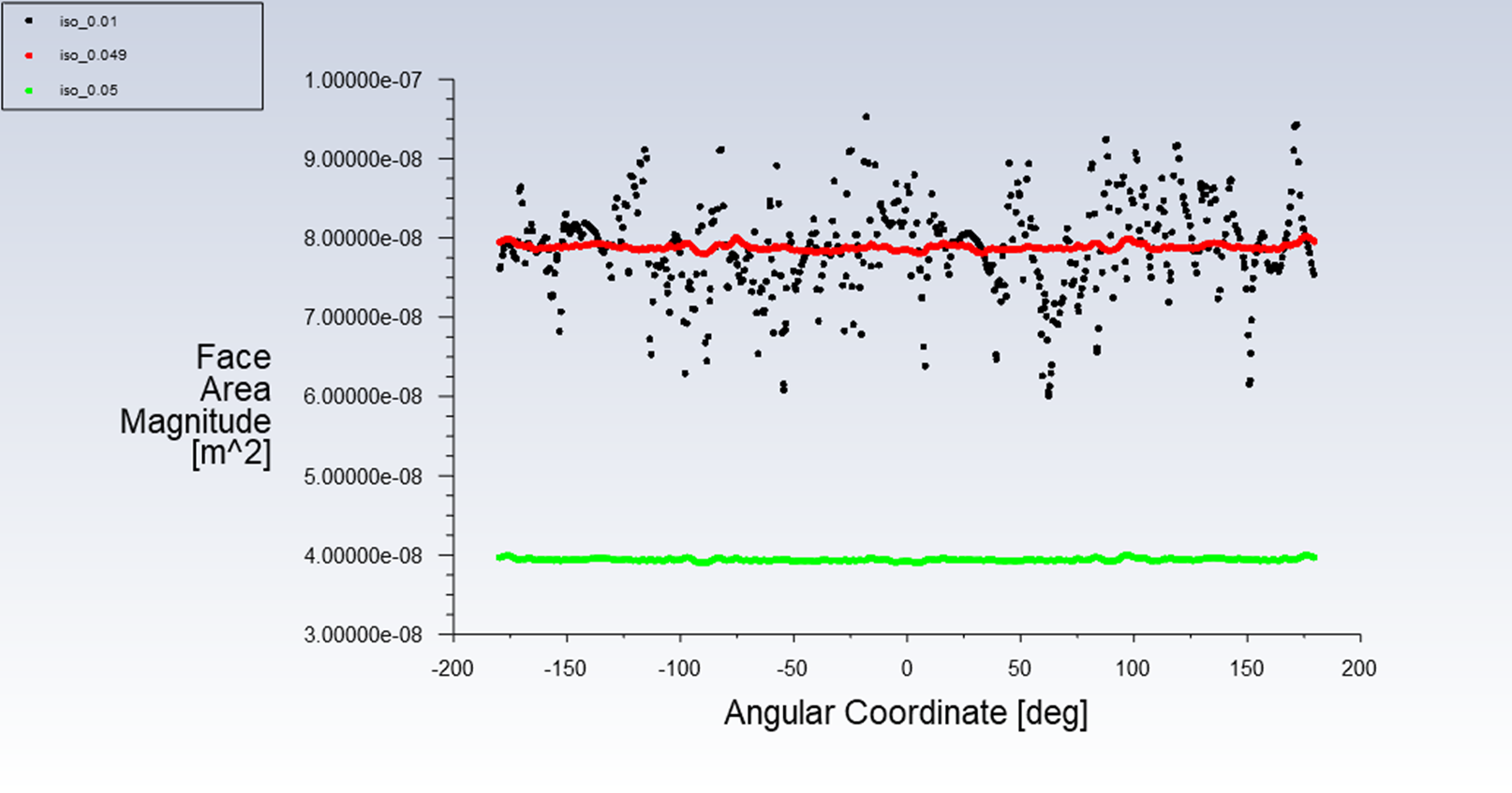
To obtain 'clean' data, I need to create the line in 3D before generating the mesh because otherwise, there is a significant amount of data dispersion. Additionally, when I create a line right next to the line drawn in the domain, the heat flow curve changes. I'm mentioning this because I don't quite understand why it happens, even though I have a relatively fine mesh in the radial direction (cell size of 0.3mm in a radius of 21.1mm). The energy convergence is on the order of 10e-7. This effect is not eliminated by drawing nodes vs. cells and worsens as the mesh becomes more distorted, as shown in the lower example.
Does anyone know why this effect occurs and how to resolve it? I often use structured meshes, and with that type of mesh, this issue doesn't arise.
Many thanks in advance!
-
October 4, 2023 at 8:08 am
Rob
Forum ModeratorCan you plot wall temperature and compare the two? Also facet area.
-
October 4, 2023 at 8:51 am
100041488
SubscriberHi, the boundary condition is a constant temperature (because I was trying to obtain the h coefficient distribution). Anyway, I plotted all the graphics. Many thanks!. The question is, what is the difference between iso lines at 0.01 versus 0.049, as the q” distribution is slightly different. Also, why are the results different for iso_0.05 (where the interface for the two fluid bodies is internal, I created it just to ensure I had 'clean data') compared to 0.049 (defined earlier), and why does 0.01 exhibit a lot of noise
-
October 4, 2023 at 9:31 am
Rob
Forum ModeratorSlightly difficult to explain as there are a few factors to consider.
- Post processing surfaces interpolate data from the adjacent cells. A pre-meshed surface (boundary condition surface) uses the data that's actually stored on that surface.
- Lines have no area, so field values are usually fairly smooth, area values may be a little less smooth.
-
October 4, 2023 at 10:16 am
100041488
SubscriberHi, thanks for the answer, but I still have a question. How should I define the mesh for the CFD problem to address this kind of issue? In this case, I need to solve for q” through the line in order to estimate the h coefficient (please remember that the boundary condition dictates constant temperature). I’ve also run the simulation in double precision, but the outcome remains the same. Also because I would like to know which of them is the right one (iso_05 or iso_049)
Regards
-
October 4, 2023 at 11:18 am
Rob
Forum ModeratorNumerically they're both right.
For a flux I'd look at cell values, so a strip of cells. It's one of (the many) reasons I teach that planning the post processing is part of the model set up. So, if you know you need data at a certain position build that into the mesh if it won't cause problems at the meshing stage.
-
October 4, 2023 at 1:07 pm
100041488
SubscriberUnderstood, many thanks for your help
-
- The topic ‘Data distortion with a non-structured mesh’ is closed to new replies.
-
3029
-
971
-
858
-
851
-
792
© 2025 Copyright ANSYS, Inc. All rights reserved.