-
-
November 20, 2021 at 4:59 pm
Baloch
SubscriberDear All,
I am doing a full transient analysis of an RCC structure. After going through to many literature about damping consideration I am now confuse what damping should I consider. Can any one simple some of the questions I have.
1) I have first three frequency of my structure along with the respective damping which 1.66 Hz/2.40 %, 5.90Hz/2.40% and 10.20Hz/1.1% respectively. How I can decide what two frequency I should select and what is the criteria for the selection calculating alpha and beta for rayleigh damping?
2) Additional, my structure is reinforced concrete so do I need to define in material data of both steel and concrete the value of alpha and beta?
3) What damping need to be consider for full transient analysis? I.e material dependent damping or rayleigh damping or any other or a combination?
Note: My analysis is a full tansient for an RCC structure having an earthquake loading.
Best regard
November 20, 2021 at 6:14 pmpeteroznewman
Subscriber1) Choose the frequencies that are closer to the excitation frequency in the transient analysis. If the excitation frequency is low, make sure the damping is correct at the low frequency and vice versa.
2) If you apply Rayleigh damping in the Analysis Settings in Transient Structural, that is a global setting and will apply to all elements in the model. There is no need to assign it in Engineering Data.
3) In fact, if you add damping in Engineering data to a material in your model, that will be additive to the global damping in the analysis. Use Rayleigh damping under analysis settings to select the best coefficients to get closest to the three values of damping for the three frequencies you show.
November 21, 2021 at 4:42 pmNovember 21, 2021 at 5:42 pmpeteroznewman
SubscriberMy advice was to not use Material Damping in Engineering Data but to use Global Damping under Analysis Settings.
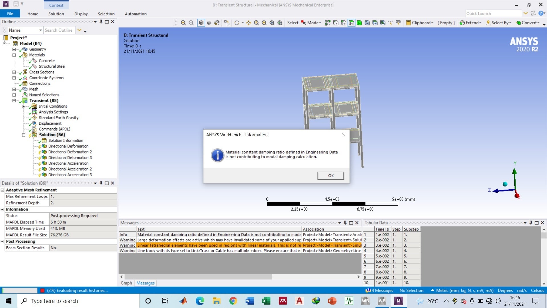
Sometimes ANSYS will issue warnings when certain conditions are detected, even though the warning doesn't apply due to other conditions being met.
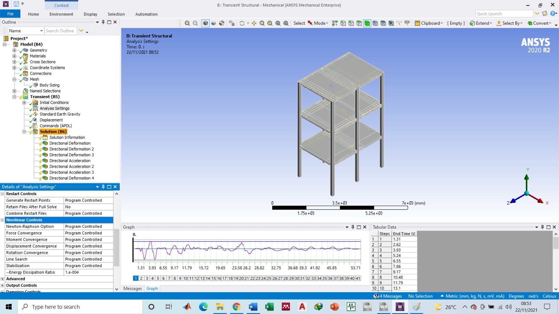
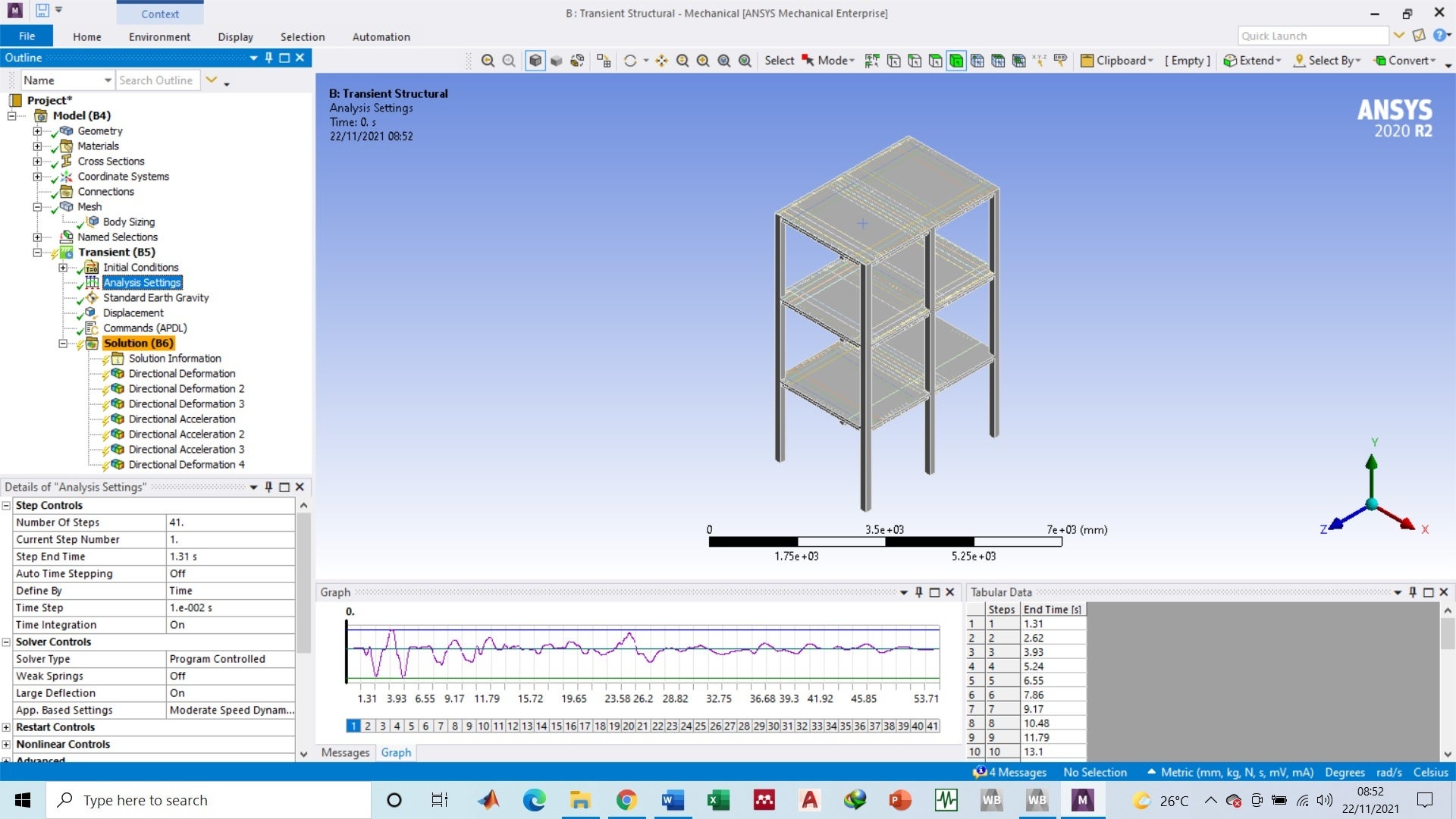
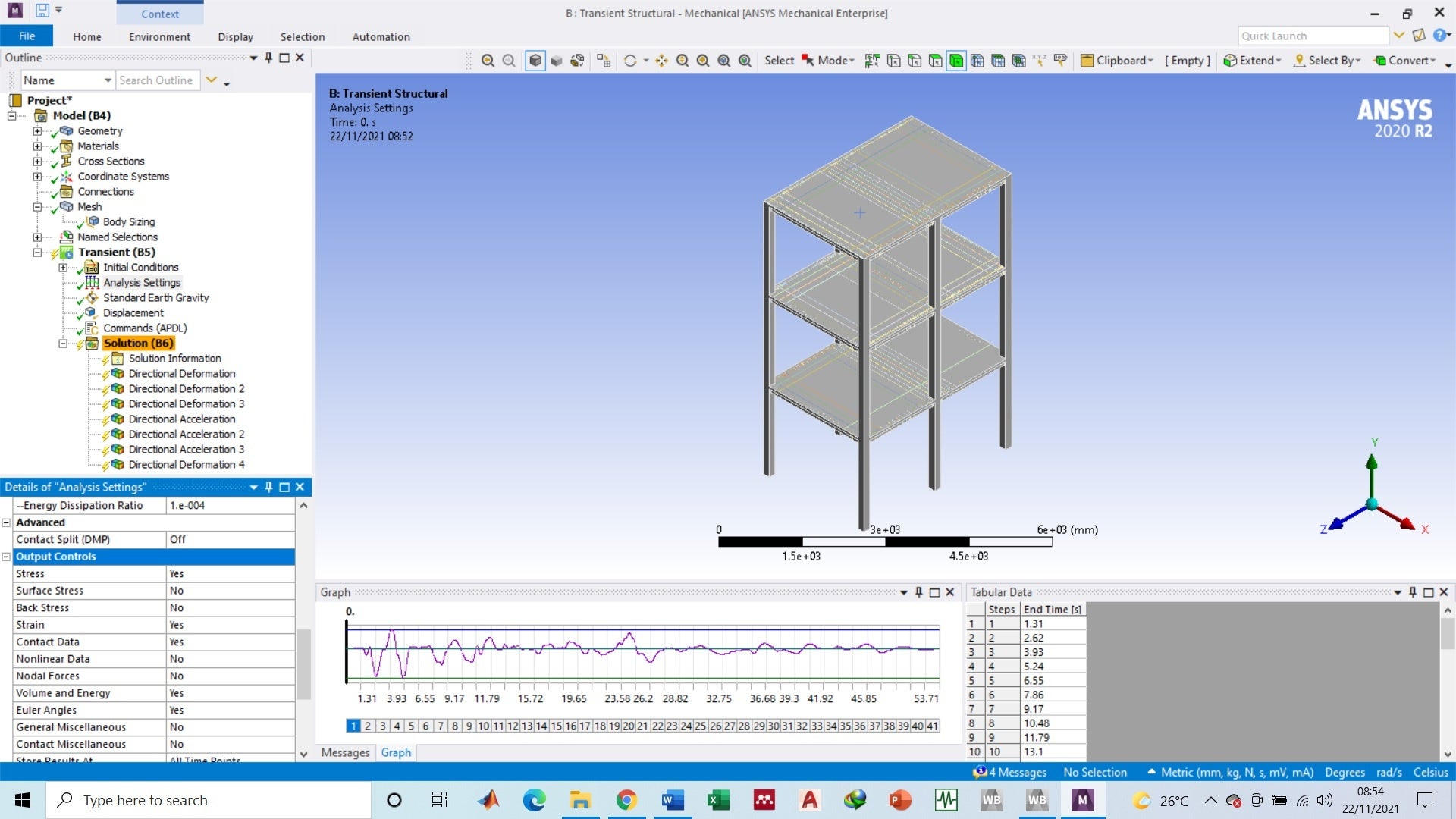
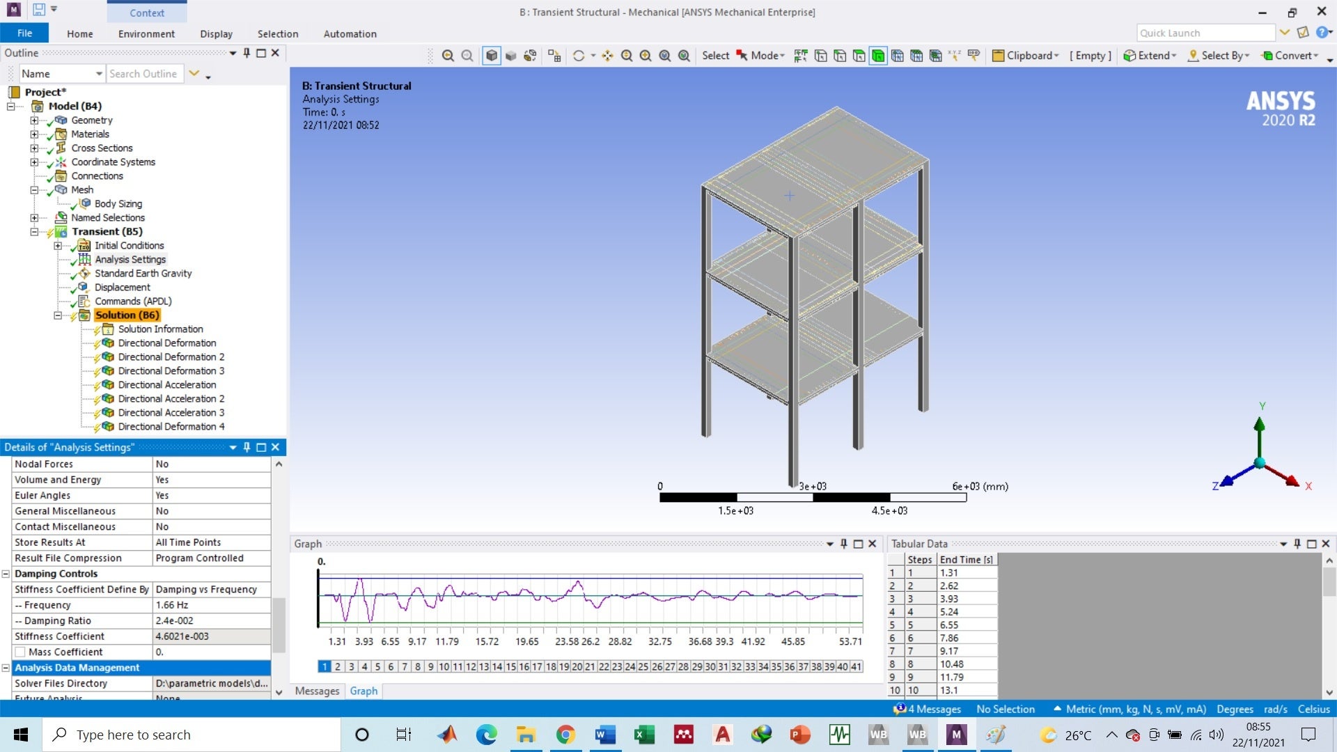
Show the Analysis Settings for this Transient Structural.
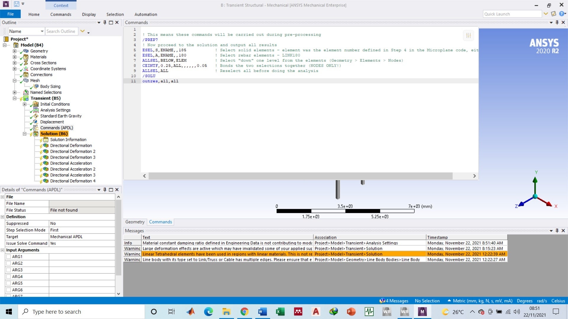
Show the APDL code you inserted.
November 22, 2021 at 1:00 amNovember 22, 2021 at 1:23 pmpeteroznewman
SubscriberYou say "I am facing the problem of rigid body motion". Do you mean a warning was issued? If the model seems to run properly, you can ignore this warning. I often get a warning when I know the model is properly constrained and it runs properly. I don't know why ANSYS generates this warning when the model is properly constrained.
Does your model run as expected or does your model not run properly?
Why did you break the solution into 41 steps?
How was the gravity load introduced? The proper way to do that is in Step 1, with Time Integration turned off, and with zero displacement in the Displacement load. Then in Step 2, turn on Time Integration and begin the Displacement load that is providing the ground motion. If you don't turn off Time Integration in step 1 to allow gravity to come to static equilibrium, time integration will compute the vertical motion of the structure as gravity is suddenly turned on or ramped on depending on the load setting. You don't want that.
What is the sample rate of the earthquake data (time increment between values in the data)?
November 22, 2021 at 4:10 pmBaloch
SubscriberBy rigid body motion I mean my structure is behaving like a rigid body, I am getting same displacement along all floor almost same as the base excitation.
Model is running properly but I am not getting the desired results which I have from an experiment.
I break the results to avoid any convergence issue since my earthquake time series has around 5000 data points.
For the gravity load yes I did the same for the step one I did not applied any excitation just allowed the gravity load to come till equilibrium and from step two I applied the excitation and gravity is then constant from step 1 till the last step.
Time step for my simple is 0.01 sec and total time is 53.71 sec.
November 22, 2021 at 4:44 pmpeteroznewman
SubscriberEarthquake data sampled at 0.01 seconds is a sampling frequency of 100 Hz, which means you should not look at frequencies above 40 Hz.
Earthquake data is recorded by accelerometers. Do you have the original acceleration vs time data?
You should compute the Shock Response Spectrum for your earthquake data and see what frequency has the largest response. I can do that if you attach the data in a zip file. Include both the displacement and the acceleration if you have both.
The concrete in your model is a nonlinear material, but you should create a linear elastic material with the same stiffness and density just so you can run a Modal analysis. If the first modal frequency of the structure is 33 Hz, but the earthquake has it's peak energy at 3 Hz and has little energy at 33 Hz, then having the building follow almost exactly the 3 Hz ground motion is what you would expect.
November 22, 2021 at 5:20 pmBaloch
SubscriberHere is the earthquake data file. The excel file has two sheets. The experimental work I am following actually did the shaking table test for 0.10g of elcentro data. One sheet the scaled data for 0.10g and one sheet is for original earthquake data for elcentro 1940.
I did the model analysis which is showing the first model frequency of my structure is around 8Hz. From the response spectra of earthquake i can see the maximum acceleration response id around 4hz . But for full time history it should pass through the resonance frequency and give a peak response on point in time through out the simulation. Please have a look on earthquake data.
November 22, 2021 at 9:27 pmpeteroznewman
SubscriberYou say that the first modal frequency of your structure is around 8 Hz, but in the opening of this discussion, you say the first mode is 1.66 Hz with 2.4% damping. Is the 1.66 Hz an experimental measurement from the lab? If so, your structural model is a long way from the experimental data.
I am familiar with the elcentro data. In fact, you are using the NS direction of the data. There is also an EW direction data set as well as an UP direction.
I use a set of scripts called vibrationdata in matlab to help manipulate data. One of the things it can do is subject a SDOF mass/spring/damper to a base input and calculate the response.
I convert the 2.4% damping you reported in the opening to a Q value of 20.83 for use in the calculation. I can use that value of damping with an 8 Hz natural frequency SDOF system and obtain the following relative displacement between the base and the mass:
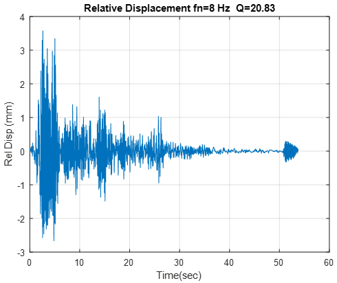 But look at the response of the mass when it has a natural frequency of 1.66 Hz. It is huge!
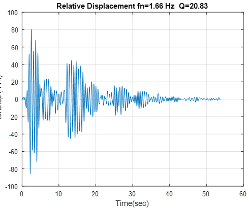 The above plots are just for illustration since you have a multiple DOF structure and not a SDOF system.
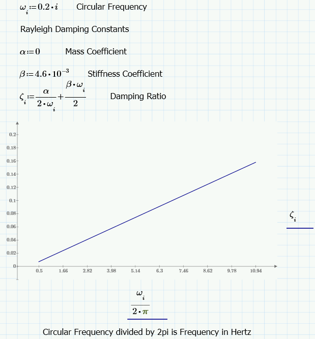
I see you applied Damping by entering Frequency and Damping Ratio, and let ANSYS compute Beta, but left Alpha at 0. This means the damping ratio will increase linearly with frequency. So while you get 2.4% Damping Ratio at 1.66 Hz, by the time you get to 10.2 Hz, the damping is up to 14.7% which is way too high!
 If you use both Alpha and Beta, you can keep the Damping relatively constant over the range of 1.66 Hz to 10.2 Hz.
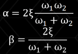
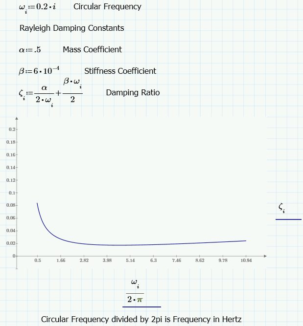 I guessed at Alpha and Beta, but you can solve for values that put two frequencies on the same value of Damping Ratio.
 November 22, 2021 at 9:57 pm
Baloch
Subscriber
Yes that 1.66 Hz is from experiments and 8Hz is for simulation I did in ANSYS.
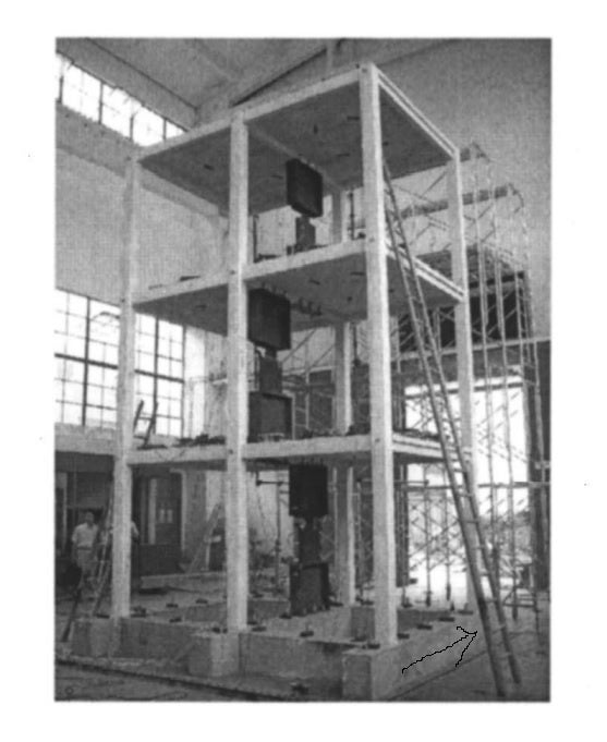
For the experiments a solid base was used to connect the structure with the shaking table which I have not included in my model because the primarily objective of the base is to excite the structure I guess. Do you think this matters? You can see in the picture I pointed the rigid base while I ignored this and directly applying excitation at column face.
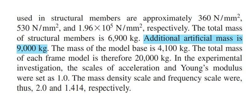
One more thing is reported by the author an "artificial mass" which is not explicit described and I could not understand what that means. It is mentioned that the have used a certain artificial mass. Do you have idea on this? and if yes How one can apply an artificial mass in WB?
November 22, 2021 at 10:20 pmpeteroznewman
SubscriberYou have to increase mass or reduce stiffness or both in order to bring the 8 Hz down to 1.66 Hz. There is no such thing as artificial mass. It sounds like the author needed to add mass to get the model to match the experiment.
Do you have mode shapes for the first three frequencies you opened with? Because you will want to tune the model to have modes as close as possible to the other two frequencies as well...
November 22, 2021 at 10:44 pmBaloch
SubscriberReferring to the author I mean the experimental work since the author mention this artificial mass for the experimental works.
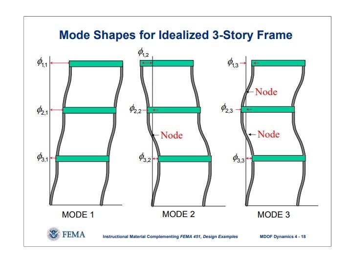
I do not have the mode shapes for the frequencies which I mentioned at the opening statement but since it is mentioned that the structure is tuned at the X-direction (X-direction refer to the direction I pointed) so the possible mode shapes may be some thing like shown in the second picture.
November 22, 2021 at 10:50 pmNovember 23, 2021 at 1:09 ampeteroznewman
SubscriberIn my work, we use the terms Structural Mass and Nonstructural Mass. If you have a building with steel reinforced concrete columns and floors, that is all considered Structural Mass. Once you add in carpet, furniture, plumbing, electrical, HVAC, that would all be considered Nonstructural Mass. Maybe artificial mass means Nonstructural Mass.
November 23, 2021 at 1:35 amBaloch
SubscriberYes thats true but in the context of this analysis I could not understand how this artificial mass he mentioned need to be considered. However, I tried to add a 9000kg point mass at the centroid of the structure and also increased the density of concrete and steel which make the structural mass greater then 9000kg than the normal one. But Both the approach didn't worked for me. It changes the acceleration responses to some extent but whenever I check the displacements its behavior is same what displacements I apply as base excitation the response displacement at the 1st, 2nd and third floor are same. It looks like its not the Problem here. Before I applied material damping in engineering data as 5% (0.05) for concrete and 2% (0.02) for steel the response is still same as rigid. And also I applied Rayleigh damping for which I applied stiffness coefficient based on 1st natural frequency and kept mass co efficient as zero since I got some reference which mentioned the mass coefficient for structural analysis can be zero for some cases but I still got the same response as a kind of rigid motion. Now my analysis is running where I used stiffness and and mass coefficient calculated using the equations you mentioned in your 3rd last comment based on 1st and 3rd natural frequency of the structure . Lets see hopefully it will work.
November 23, 2021 at 4:43 ampeteroznewman
SubscriberFirst priority is to get the first three modal frequencies of the model to be much closer to the three frequencies from the experiment.
After you have that accomplished, then you can look at damping. Playing with the damping isn't going to get an 8 Hz structure to behave like a 1.66 Hz structure.
November 23, 2021 at 12:06 pmpeteroznewman
SubscriberOne place where the stiffness of your model is too high is the bottom of the columns. The model has a boundary condition on the bottom of the column that is infinitely stiff. The real column bottom goes into a base providing flexibility to the bottom of the column. You can add flexibility to the model by introducing a rotational spring between the bottom of a column and a rigid body to represent the base. The displacement is then applied to the base.
Viewing 17 reply threads- The topic ‘Damping consideration in ANSYS.’ is closed to new replies.
Innovation SpaceTrending discussionsTop Contributors-
5004
-
1681
-
1387
-
1248
-
1021
Top Rated Tags© 2026 Copyright ANSYS, Inc. All rights reserved.
Ansys does not support the usage of unauthorized Ansys software. Please visit www.ansys.com to obtain an official distribution.
-
Ansys Assistant will be unavailable on the Learning Forum starting January 30. An upgraded version is coming soon. We apologize for any inconvenience and appreciate your patience. Stay tuned for updates.

