-
-
March 14, 2023 at 3:23 pm
murali macharla
SubscriberHello Everyone,
I am performing the creep simulations and i am constantly getting error saying that creep limit ratio is exceeded and the analysis is stopped. I have tried all the creep limit ratios from 1 to 100 and i am still getting the error. Is there anyway to calculate the creep limit ratio ? and how should i achieve convergence here. Please someone help me .
Best regards,
Murali.
-
March 14, 2023 at 3:44 pm
peteroznewman
SubscriberHello Murali,
Have you turned on Auto Time Stepping?
Did you set it to time substeps?
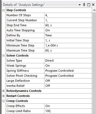
What values did you use for Inital, Min and Max time substeps?
The corrective action is force the solver to use small time substeps on the Max time substep.
The Min time substep can be 100 times smaller than the Max time substep.
The Initial time substep can be equal to the Max time substep.
-
March 15, 2023 at 10:06 am
murali macharla
Subscriber
-
-
March 14, 2023 at 3:54 pm
-
March 15, 2023 at 11:46 am
peteroznewman
SubscriberWhat load is applied in step 1?
If you turn creep effects off, what is the maximum stress at the end of step 1?
-
March 15, 2023 at 12:01 pm
murali macharla
SubscriberHello Peteroznewman,
In all steps, the only load applied is temperature. In the first step, the applied temperature is 280c.
In the next steps, it is cooling down to room temperature from 280c.
If i turn creep effects off, the stress(Von mises) at the end of step 1 is 128 MPa.
-
-
March 15, 2023 at 1:02 pm
peteroznewman
SubscriberWhat is the environment temperature?
What is the reference temperature of all the materials?
Is the step 1 temperature load Step Applied or Ramped up from the Environment temperature?
Try using Initial Time Step of 1e-4 s.
Turn on Large Deflection.
Turn off Weak Springs (why would you need them?)
-
March 15, 2023 at 1:21 pm
murali macharla
SubscriberThe environment temperature is 280c.
The reference temperature of all materials is 22c.
In step 1, the load is same as environment temperature i.e., 280c. In step 1 , the load(280c) is kept constant for 1 minute. Then it is ramped down in other steps.
I have already used the initial step as 1e-4, still not converging. I even went till 1e-8, there is no convergence.
Ok i will turn on large deflection and run the simulation.
I added week springs as i am performing simulation on chip and substrate bonded with interconnect. Here they attach through bonded contacts. So, i turned on weak springs. And i also need to check warpage of chip and substrate, so it doesn't make sense to give boundary conditions.
And yeah i am using only direct solver.
-
-
March 15, 2023 at 2:37 pm
peteroznewman
SubscriberIf you are assembling parts at 280C then want to monitor the creep as it cools down, both the material reference temperature in the CTE definition and the environment temperature should be 280C so that there is zero strain at 280C at the beginning of the simulation.
In that case, step 1 would not be a temperature load of 280C, it would be whatever temperature you want to cool down to.
-
March 15, 2023 at 2:52 pm
murali macharla
Subscriberso, in step 1 if i keep room temperature of 22c and time of 5 minutes as it is our cool down time. There is no need of adding any other time steps and temperature ?. Will that be enough to observe creep in cool down process?.
-
-
March 15, 2023 at 4:42 pm
peteroznewman
SubscriberYou want two load steps. Step 1 with a ramped temperature load of 22 C and an end time of 300 s to cool down over 5 minutes. Then a second load step to track continuation of creep for as long as you are interested with the temperature constant at 22 C. Could be an end time of 86,400 s to look at the creep after 24 hours.
Auto Time Stepping will ensure creep is accurately captured during the first 5 minutes and the 24 hours. You might have different Minimum and Maximum Time Step sizes for step 1 and step 2. Carry over time step may be a good choice.
-
March 16, 2023 at 8:22 am
murali macharla
SubscriberI made the changes as you said and the simulation is running. But, with 12 cores itself, it took 14 hrs to calculate just 3 seconds (still ansys need to calculate creep for 597 seconds), and it has generated almost 40 GB of data for those 3 seconds. I am not sure why it is like that. is there anything i am doing wrong. I have following settings.
I am using 'direct solver'.
weak springs 'on'
creep limit ratio is ' 100' . (any value below 100 is not making the simulation to run)
Initial time step : 1s
Min time step : 1e-4s (simulation is not running for )
Max time step: 40s
Environment temperature : 280c
Will be waiting for your reply.
-
-
March 16, 2023 at 5:15 pm
peteroznewman
SubscriberIf the computer has only 12 cores, using all of them does not deliver the shortest possible solve time. Use one less than every core. There is also diminishing returns, so the solve time might not be much longer at 8 cores than 11 cores.
The number of nodes and elements in the simulation has a significant impact on the solve time per iteration. You could use a coaser mesh and cut the number of nodes and elements in half by increasing the element size. The ideal mesh uses smaller elements where the result change rapidly, either in time or location and larger elements where the results change slowly in time or location.
The time it takes to solve a transient model is proportional to how many iterations it must make. That is determined by the convergence criterion you impose on the solution. If you give it a small convergence tolerance, it will need more iterations, if you provide a larger convergence tolerance it will do fewer iterations.
The step controls is a place where you might have used a smaller value for Max time step when the solver would have been happy with a larger value. That does not seem to apply to your situation.
Just because the first 3 seconds took 14 hours, doesn’t mean you can linearly extrapolate to estimate the solution time for 600 seconds because the rate of change exponentially decreases and when it does, the time steps will get much larger and it might only need a few more hours to finish.
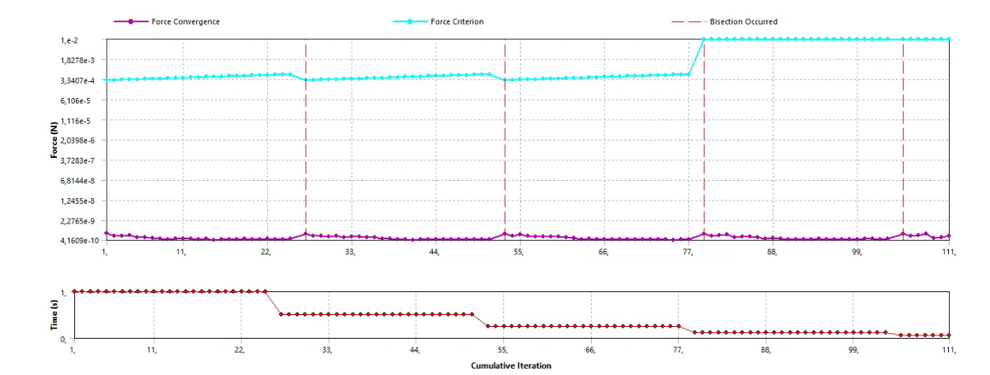
Click on the Solution Information folder. In the Details window is the Solution Output. The default setting is Solver Output. That is all text, but sometimes you get a clue as to what criterion is limiting the size of the step. Change the setting to Time Increment. On this graph, you can see if the solver is bumping up against a Min or Max Time Step limit you imposed, or if it is choosing the best Time Step it has decided on.
You can control how much output you are getting by clicking on Analysis Settings and going to the Output Controls category. Do you need both Stress and Strain? If not, turn off the one you don’t need. Change Store Results At to Equally Spaced Points and type in 300, then you will only get results on a 2 second increment over the 600 second end time.
What version of ANSYS are you using? Year and R#.
If you can share your model, use File Save As to a new name. In workbench right click on Model and select Clear Generated Data. That will delete the mesh, then File Save. Next do File Archive to create a .wbpz file choosing No Results and put that file on a File Share site like Googe Drive or OneDrive.
-
March 24, 2023 at 2:29 pm
murali macharla
SubscriberHello sir,
I took so many days as i need to delete some information and need to send that model . Please go through the model.
https://drive.google.com/file/d/1aa7JUpMjCjEF-trFau_ogqbBYkglRqd2/view?usp=share_link
I ran the model after making changes according to you. It took 6 days but i can able to save the space after changing the output controls.
I am using Ansys version 2019 and R3.
Best Regards,
Murali
-
-
March 24, 2023 at 7:15 pm
peteroznewman
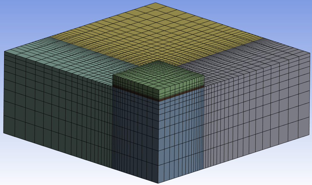
Subscriber- You should take advantage of 2 planes of symmetry and do a 1/4 model.

- In SpaceClaim, on the Workbench tab, click the Share button, then in mechanical, delete all the contacts.
- Instead of a single layer of quadratic Tetrahedrons, use Linear Hex Elements and put 4 through the thickness of the creep layer.
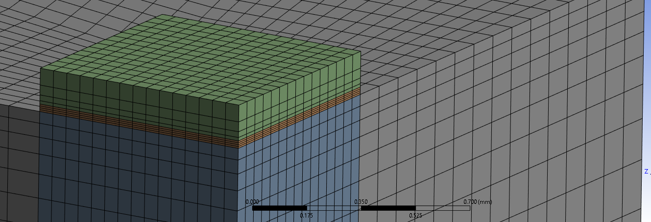
- I will reply with other comments after I run the simulation.
- You should take advantage of 2 planes of symmetry and do a 1/4 model.
-
March 25, 2023 at 2:55 pm
peteroznewman
SubscriberI don’t have Ansys 2019 so I ran my model on Ansys 2022 R2.
I needed to correct all the Reference Temperatures in Engineering Data to 280 C and the Silicon has a Zero-Thermal-Strain Reference Temperature of 217 C which I made 280 C.
I changed the simulation to a single step of 600 seconds, with data written out 300 times (every 2 seconds). Under Analysis Settings, the Creep Limit Ratio was 3000, and Nonlinear Data was set to Yes. Initial Time Step 0.1s, Minimum Time Step 1e-6s, Maximum Time Step 10s. The solver determined that the time step had to be 4e-5s to maintain the creep ration below the limit.
I let my 4-core laptop run overnight for 13h 17m while it performed 15,166 iterations to simulate 2.16 seconds. The mesh has 12,619 nodes and 10,800 elements. Unfortunately, with a linear change in the temperature, I don't expect the time step will change, which means this model would need 153 days to get to 600 seconds! See my next reply on a change in the thermal boundary conditions that would probably allow larger time steps as the cooling occured.
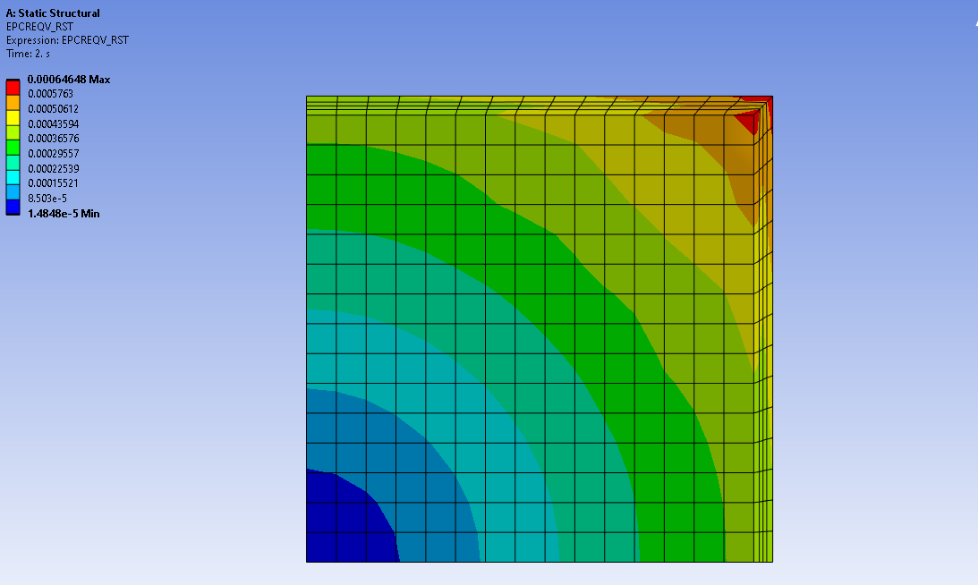
I created a User Defined Results as highlighted below, scoped to just the body with the creep material.
Looking up from below, at the 2 second mark we see the eqivalent creep strain.
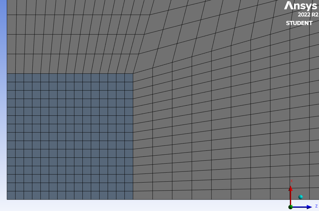
Seeing this gave me an idea that the mesh on the center column of the silicon, creep copper and base copper t hat I should have biased the elements size to put smaller elements toward the edges and larger elements toward the center, which is the lower left corner of these images. I would also split the large L-shaped block into 3 blocks to improve the element shapes from this:
To this:
-
March 27, 2023 at 8:41 am
murali macharla
SubscriberHello peteroznewman,
Thanks a lot for the review and your time. I am running my model by making the changes you have mentioned. could you please attach the simulation you performed , i would update ansys and want to see the stresses and user defined results i want.
-
-
March 25, 2023 at 3:26 pm
peteroznewman
SubscriberI tried Convective cooling on the outer surfaces only and I found that copper is so great of a conductor of heat that the temperature throughout the model goes down so rapidly that it matches the air temperature in seconds. If you are simulating an oven with a controlled cool down ramp, you have a good load definition.
-
March 27, 2023 at 9:25 am
murali macharla
SubscriberThe first 300 seconds is in oven and the next 300 seconds is in room temperature i..e, convective cooling. So, as you said that copper is cooling down very quickly in air. i can reduce the second step from 300 seconds to 150 seconds.
-
-
- The topic ‘Creep limit ratio is exceeded and analysis stopped’ is closed to new replies.


-
5074
-
1813
-
1387
-
1248
-
1021

© 2026 Copyright ANSYS, Inc. All rights reserved.

