TAGGED: #Modal_Analysis, acoustic-modal, contact, mechanical
-
-
August 6, 2024 at 2:15 pm
DevenM
SubscriberI am trying to create a no penetration contact between two bodies with an initial separation between them in modal acoustics analysis. This is however, very hard to establish because Ansys tries to create the contact based on the initial separation and having a bonded or a no-separation contact would be incorrect in my case. So how do I create contacts between bodies which are far away to begin with but come in contact during the analysis process? This is easily done in static structural but do you guys know how I could do that for modal?
-
August 7, 2024 at 6:23 am
Kaushal Vadnere
Ansys EmployeeHi Deven,
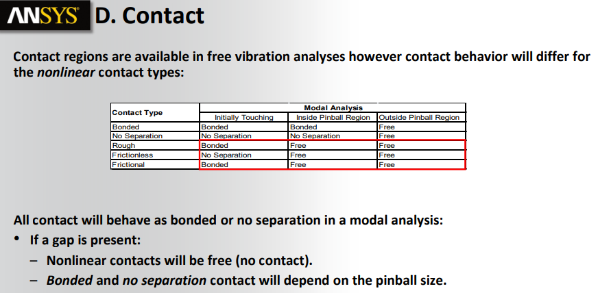
To model contact between 2 bodies which have intial seperation, you can use ‘stabilization damping factor’ in contact. The stabilization damping factor provides a certain resistance to damp the relative motion between the contacting surfaces and prevents rigid body motion. The stabilization damping factor works similar as defining a spring between 2 bodies with a very small stiffness which will hold the bodies together without significantly affecting the stiffness of the system.
You can create manual contacts to overcome your issue with automatic contacts.
For no penetration, you can use ‘Normal Lagrange’ formulation. Normal lagrange enforces zero penetration when contact is closed making use of a Lagrange multiplier on the normal direction and a penalty method in the tangential direction. Refer to this article in Ansys help for more info on Advanced contact settings: 9.6.3.3. Advanced Settings (ansys.com)
All these settings work for prestress static analysis.You can take these FREE ansys innovation courses to learn more about contact mechanics and best practices: Rigid Body Motion in Contact | Ansys Innovation Courses, Fundamental Topics in Contact | Ansys Innovation Courses, Contact Mechanics | Ansys Innovation Courses
-
August 7, 2024 at 12:46 pm
-
August 9, 2024 at 9:21 am
Kaushal Vadnere
Ansys EmployeeClarity on my first answer: Modal analysis being a purely linear dynamic analysis, any non-linearities present are either ignored or reduced to their linear counterparts (such as non-linear contacts with initial seperation are set as free). To account for non-linearities, you will need to perform a static analysis and use it as prestress condition. Also, as you mentioned, the bodies will come in contact during the analysis, deformation effects are not valid in modal anaysis, you will need to perform a static analysis for deformations.
Apart from that, I have few question regarding your model,
1. Just to confirm, are you performing a modal structural analysis or modal acoustic analysis?
2. Can you share what are goals and objectives of your analysis, you can share screenshots and probably a diagram of your system with annotation to show what exactly you are trying to simulate. -
August 9, 2024 at 3:34 pm
DevenM
SubscriberHi Kaushal,
- I am performing modal acoustics analysis
- The goal is to see the modes for a fluid sloshing inside a spherical diaphragm tank. See Image attached from [Sabaghzadeh, 2021]. The fluid is modeled using FLUID221 acoustics elements and the rest of it is solid. As you can see there is a large gap between the diaphragm (inside the tank) and the tank upper half. The other side of the diaphragm (lower side) is filled with fluid. So I am trying to create a contact between the diaphragm upper surface and the tank upper half section so that the diaphragm does not go out of the tank in any of the modes.

-
August 13, 2024 at 4:34 pm
wrbulat
Ansys EmployeeHi Deven. Thank you for the image and for clarifying your objective. Using standard surface-to-surface contact between two structures (the top surface of the diaphragm and the lower surface of the top of the tank) is certainly fair game - I don't see a problem defining and using that. But if your expectation is for this contact to change status (e.g., open to closed) when deformation closes the gap in a modal analysis, well... I'm afraid that won't happen. As Kaushal mentioned, modal analyses are linear. Standard contact is not. Furthermore, the subsurface mesh of acoustic elements will not model the relatively large displacement I imagine the subsurface volume of liquid will in the physical system. Acoustic elements are probably not a good fit for what you intend to do. I think a better approach would be to model the fluid with hydrostatic elements:
I suspect these are still not natively exposed in Mechanical. We once had an ACT that simplified the addition of these to models in Mechanical but I do not know if it works with later releases. You can always use APDL command objects to add them to a Mechanical model but that assumes you have good enough background in APDL to do so.
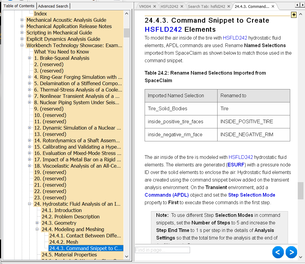
Oh... look what I just found in teh doc:

So if there's no free surface (the lower surface of the diaphragm is always "wet") then I think HSFLD242 in a transient analysis will represent this physical system with higher fidelity... it's much more appropriate. I don't see any option other than doing a full transient analysis if you intend to include the effect of possible contact between the diaphragm and the top of the vessel.
Best,
Bill
-
August 14, 2024 at 4:44 pm
DevenM
SubscriberHi wrbulat,
Thank you for your answer. I will definitely try the things that you have suggested here. Unfortunately I am not able to find the hydrostatic example that you have shown here in the workbench technology showcase examples. Could you please share a link of the same ?
Thanks!
-
August 14, 2024 at 4:57 pm
Kaushal Vadnere
Ansys Employeehere is the link to the technology showcase example: Chapter 24: Hydrostatic Fluid Analysis of an Inflating and Rolling Tire (ansys.com)
Incase, you are not able to open this link, you can launch Ansys Help from start and search the title there.
Thanks!
-
-
- You must be logged in to reply to this topic.


-
4924
-
1618
-
1386
-
1242
-
1021

© 2026 Copyright ANSYS, Inc. All rights reserved.


