-
-
December 29, 2022 at 7:03 pm
Bryce Teaford
SubscriberHello,
I have been recently working with another electromagnetic simulation software that allows for the creation of stranded coils from solid parts and was wondering how I could do this with Ansys.
For example, in the other software, all I have to do is add a hollow cylinder to the assembly and define a face within its rectangular cross section as the entry and exit terminal. Then I define how many wires are in that cross section and their gauge or fill factor.
All the examples I have seen in the Ansys help pdf show very complicated windings and I just need a simple multilayered coil. I was wondering if anyone can point me the right direction. Any help would be much appreciated!
Thank you! -
January 5, 2023 at 11:46 am
NKC
Forum ModeratorHi Bryce,
I assume you are talking about Ansys Maxwell.
You can go through the getting started guides in the Ansys Maxwell help section to understand how to create and assign turns to a solid structure.
It is similar to what you described in another software. There are some differences between 2D and 3D simulations.
Please refer to the below help files.

Regards,
Navya
-
January 5, 2023 at 11:56 am
NKC
Forum ModeratorIf it is a single coil you can directly select the coil 2D surface(you need to create the 2D surface out of the 3D coil it is 3D simulation)>Right mouse click>assign excitation and current. Here the current assignment is equal to the mmf = Number of turns x current.
If you are defining a winding with multiple coils. you need to define the coils with number of turns as explained below and then group them as winding under Excitation in the project manager window.
In 2D you can select the 2D surface of the coil >Right mouse click>Assign excitation>coil
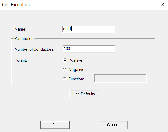
then on the popup window you can define number of conductors on the coil
In 3D it is the same, but you need to create the 2D sections before assigning the excitation.
Please refer to the help file I have mentioned above.
Regards,
Navya
-
January 9, 2023 at 7:17 pm
Bryce Teaford
SubscriberHello Navya,
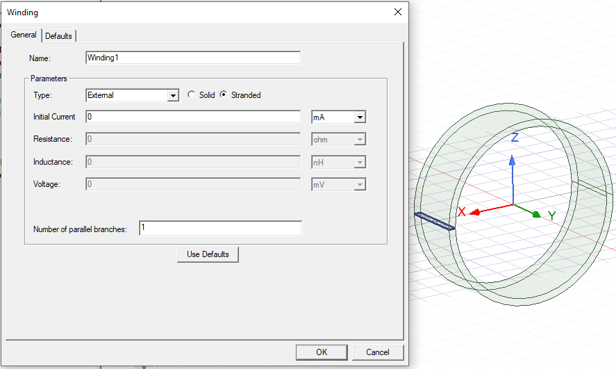
Apologies, yes I am working with Ansys Maxwell. I also would like to say I have already walked through the provided tutorial before I submitted these questions. I have provided a screenshot of my coil below with its desired terminal in pink. I have also provided the assignments of the coil as well.
In the end, this project needs to simulate a magnet a magnet oscillating in a coil that is in series with a resistor. So the excitiation of the coil will be external. The coil needs to be a 250 turn coil of gauge 30 wire. The volume I have defined are the dimensions of a coil I have already created and ran experiments with. The problem I am having with the coil is I see no way to define the coil’s gauge or filling factor, which is important to my calculations. Does Ansys have a way, when defining the coil’s number of conductors (or turns), to also define the gauge of the wire or how much space the wire will take up (filling factor).
Thank you for your time.
Best,
Bryce
-
-
January 5, 2023 at 7:13 pm
Bryce Teaford
Subscriber -
January 10, 2023 at 9:36 pm
HDLI
Ansys EmployeeHello Bryce,
I think you want to calculate current with resistance of coil in the simulation, is it?
If Yes, you have to estimate the resistance manually while using "stranded". Thanks.
-
January 11, 2023 at 6:01 pm
Bryce Teaford
SubscriberHello HDLI,
In the end, I want this simulation to provide me with the force acting on the coil while the magnet oscillates within and the current or voltage going through a resistor in series with the coil. I do not specifically need the voltage in the coil, I need the current in the circuit.
Thanks.
-
-
January 11, 2023 at 6:14 pm
HDLI
Ansys EmployeeHello Bryce,
OK. We could use current source in the circuit and the resistance would not affect the force results, so we do not need the resistance value with current source and just need "number of conductor".
HDLI
-
January 11, 2023 at 6:24 pm
Bryce Teaford
SubscriberHello HDLI,
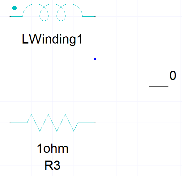
I think you are thinking of this like it is a motor being driven by the coil. My apologies for not explaining it well. This is a generator or a linear alternator. The magnet is being driven by an outside force at a constant oscillation and the circuit's current comes from the inductive force of the magnet on the coil. When you put different resistive loads in the circuit (shown below), the force that will oppose the motion of the magnet will change because the current does and both should be able to be calculated by the software if my understanding is correct.
Bryce
-
-
January 11, 2023 at 6:34 pm
HDLI
Ansys EmployeeHello Bryce,
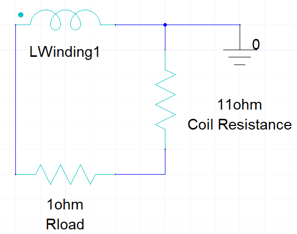
For this generator circuit, we have to add the coil resistance in series while R3 is load resistance. The coil resistance could be estimated with geometry, wire size and others by the user. The indutance will be included in the LWinding1 and automatically calculated in the FEA model.
HDLI
-
January 11, 2023 at 6:56 pm
-
-
January 23, 2023 at 2:04 pm
Pavel Piatrou
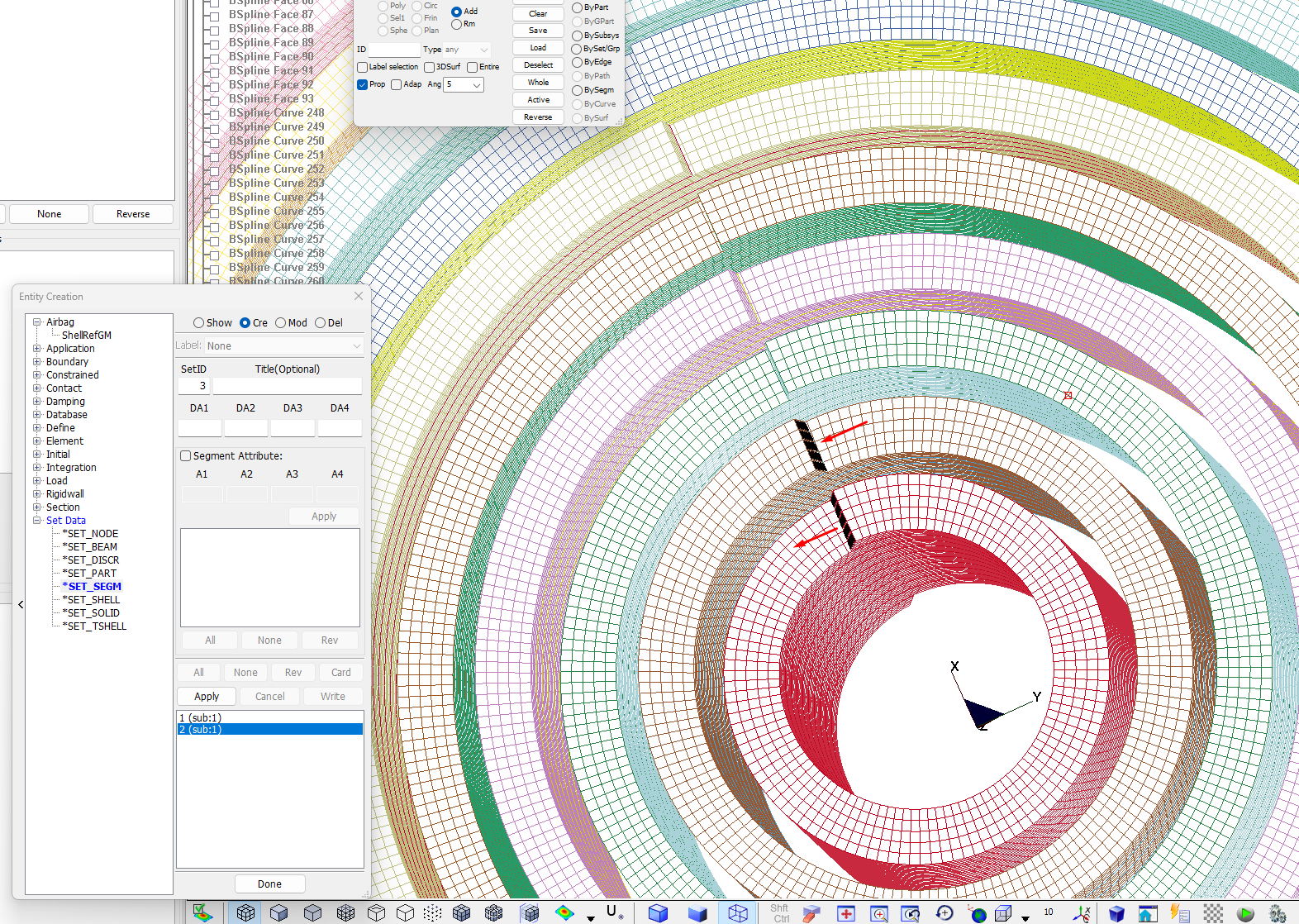
SubscriberHello everyone! I am a new user of LS-prepost. I'm trying to simulate the Lorentz force inside a multilayer coil in LS-prepost. I have drawn ten layers and now my question is it possible to assign selected segments at the end of the turns that the current passes from one layer to another (as shown in the attached picture)? The segments of the lower layer is the current output. And in the upper layer segments this current is input.
Or may be you can show links about another way to simulate a multilayer coil?
-
- The topic ‘Creating a Simple Multilayered Coil of a Specific Gauge Wire’ is closed to new replies.


- Three-Phase Voltage Imbalances in dual stator electric generator
- Co-simulation in Q3D, Icepak – meshing problem
- Classic Icepak – clarifications on Boundary condition
- Link the Circuit to 3D Terminals
- Magnetic Dipole moment calculation
- Integration lines or U Axis Line for circular and rectangular ports
- Core Loss in ANSYS MAXWELL Eddy Current solution
- exporting and importing my Netlist for my external circuit
- Error of Metal Fraction in Icepak Classic.
- The unit of theta in Is*sin(2*pi*fre*Time+theta-2*pi/3)

-
4597
-
1495
-
1386
-
1209
-
1021

© 2025 Copyright ANSYS, Inc. All rights reserved.

