-
-
September 28, 2024 at 3:35 am
engr.rohan7
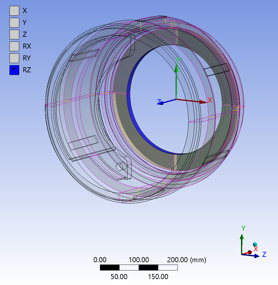
SubscriberHello community, I am trying to run a coupled field transient analysis for brakedrum. I've defined joint forces and thermal loads on brakedrum and I've also defined a couple of frictional contacts alongwith bonded contacts. Following are the screenshots for the contacts and structural and thermal loads.
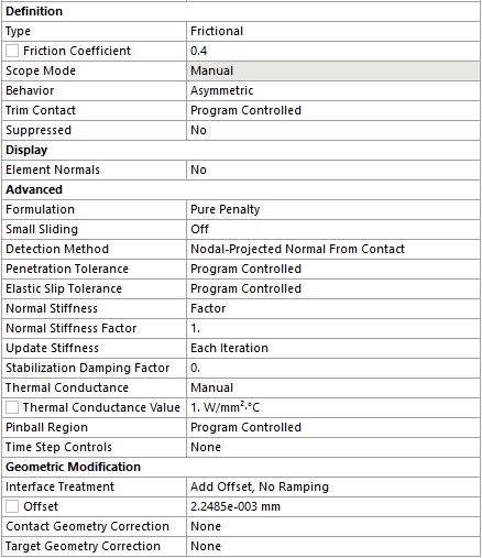
1) Contacts:- Frictional contact
The offset in the geometric modification field is defined after determining the gap using the initial info from contact tool.
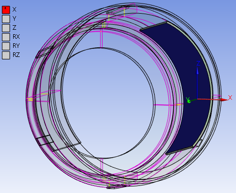
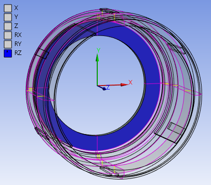
2) Joints:
a) Translational joint
b) Revolute joint
I have also created a contact tool, for which the initial information is as follows,
3) Loads are as follows,
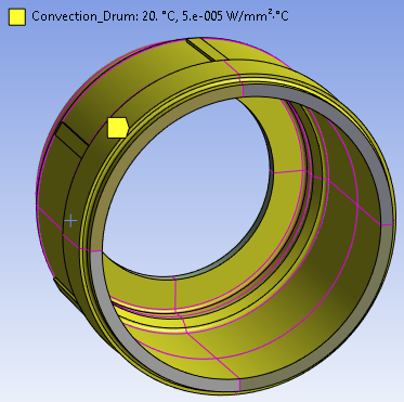
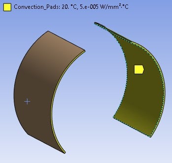
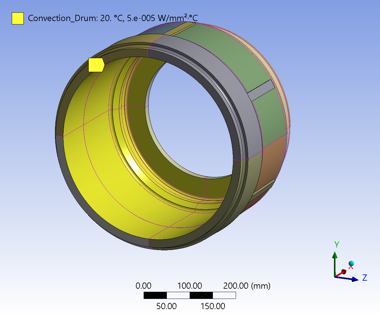
a) Convection on brakedrum
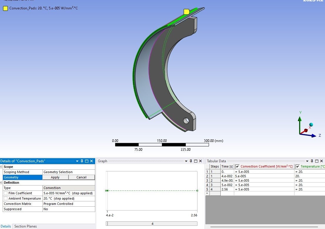
4) Convection on brakepad
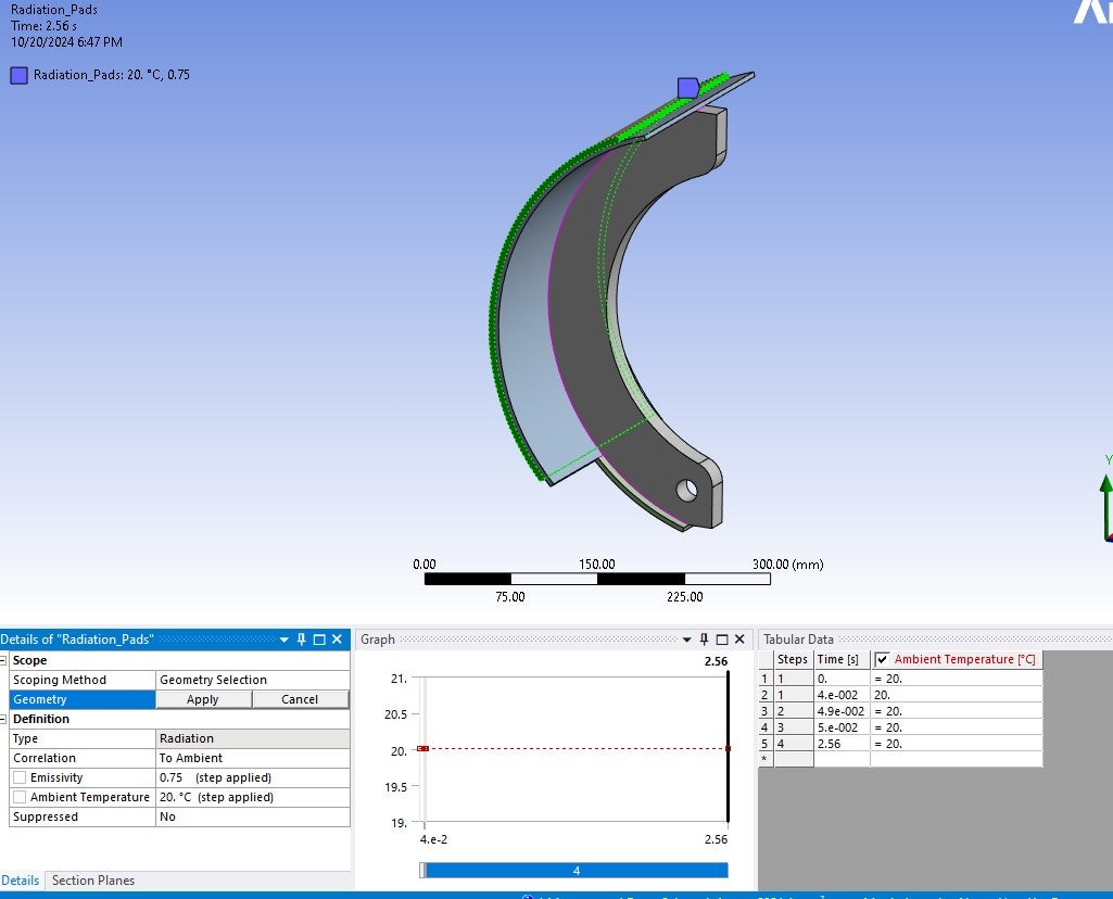
5) Radiation on pads
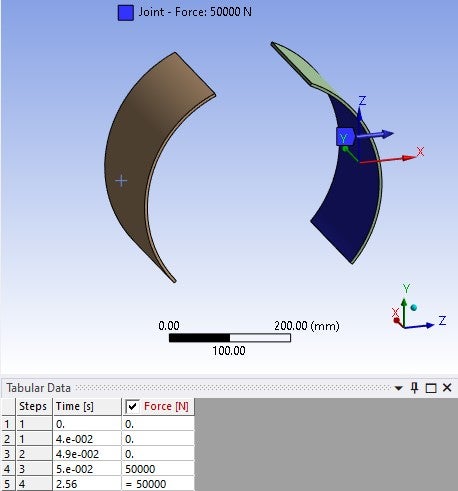
6) Joint load- force, on brakepad
Similarly defined for other brakepad.
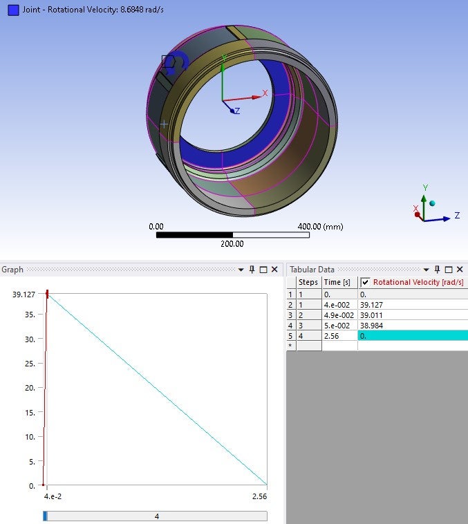
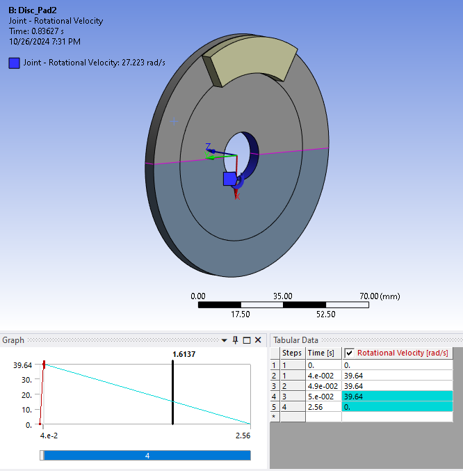
7) Joint load- rotational velocity
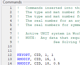
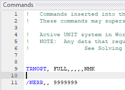
As per the video tutorial for thermomechanical analysis of disc brake by Ansys, I've also created command snippets for contacts and transient analysis
I would like to know whether the above defined contacts , loads and boundary conditions are correct.
Looking forward to your reply.
Regards,
Rohan.
-
September 29, 2024 at 12:21 pm
peteroznewman
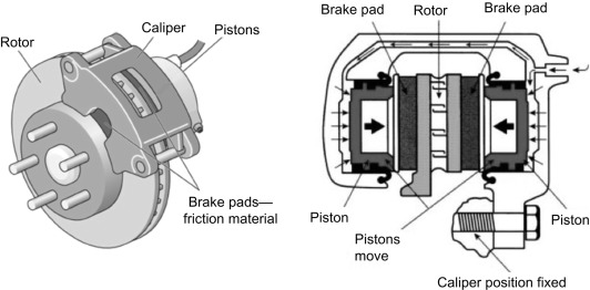
SubscriberThis site shows how drum brakes operate. Pads are on shoes that pivot about one end and are actuated by a piston at the other end. A fairly accurate simulation of this design would be to put the pads on shoes and use a joint on one end to create the pivot and a force on the other end to push the pad against the drum.
Your model has pads connected to ground by a Translational Joint which creates a slightly different motion than pivoting the pads about one end. Your model has no shoe so the pad are defined as either Rigid or Deformable. Which one did you choose? Each one introduces some error relative to modeling the shoe.
Pads conduct heat to the shoe so it is inaccurate to have convection or radiation heat transfer from the inner pad face.
It’s fine to make an initial model that idealizes the mechanism to make a model that is quicker and easier to simulate. Just be aware that a real brakedrum is more complicated than that.
-
October 5, 2024 at 12:38 pm
engr.rohan7
SubscriberHello Peter,
Thank you for sharing the link for brake working principle. It was helpful in understanding the working of brakes.
Regarding the translational joint the brakepad is defined as rigid.
The main area of interest for this analysis is determining equivalent stress and total deformation in brakedrum. So should I still go ahead and model the brakepad- brakeshoe assembly?
Regards,
Rohan.
-
October 5, 2024 at 4:06 pm
peteroznewman
SubscriberSince the main area of interest is the brakedrum, I think you have to add the shoe and appropriate joints to the model to get accurate stress and defomation in the drum.
-
October 20, 2024 at 2:05 pm
engr.rohan7
SubscriberHello Peter,
Thank you for your valuable feedback.
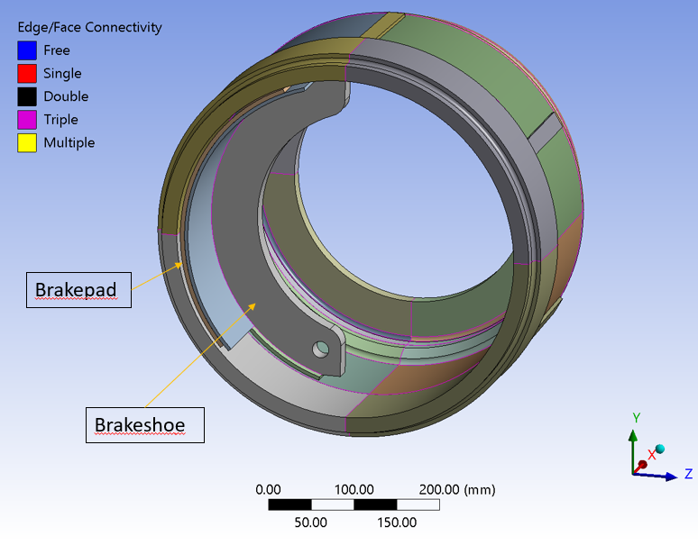
As per your recommendation, I've modelled the brakeshoe-brakepad assembly as shown below,
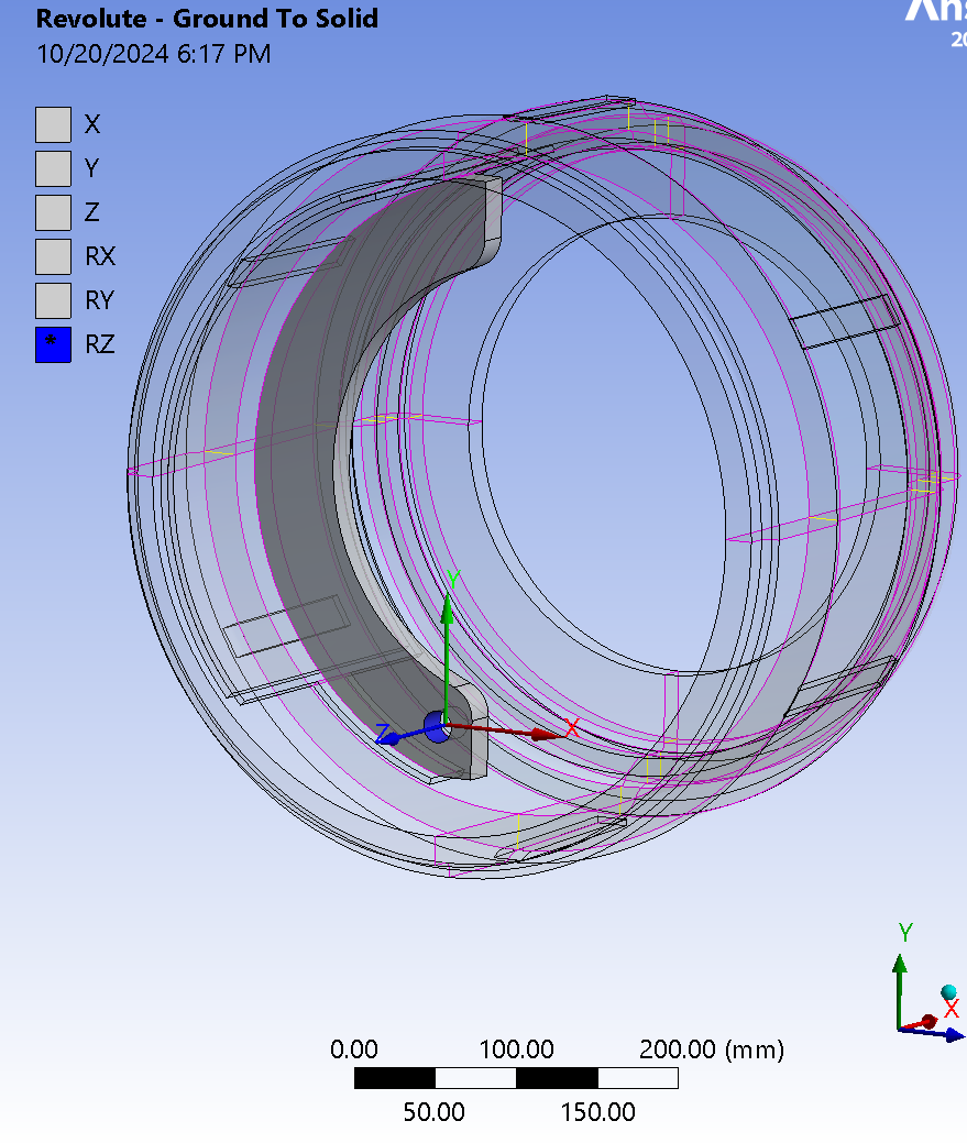
The frictional contact is same as given in the previous discussion. A revolute joint is given as a pivot for brakeshoe shown below,
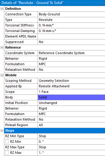
The details for the above revolute joint are shown below,
Brakedrum revolute joint-
Bonded contact is defined between pad and shoe interface.
Thermal loads are defined as follows,
Radiation on pads-
Convection on pads-
Convection brakedrum-
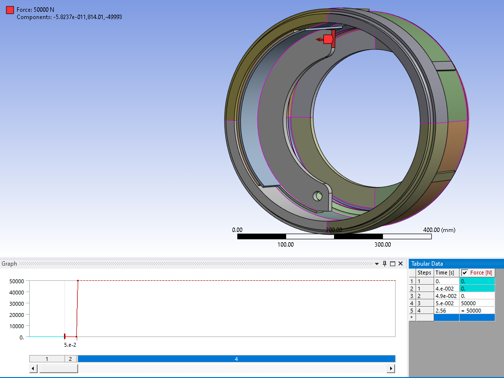
Force is given at top end of brakeshoe-
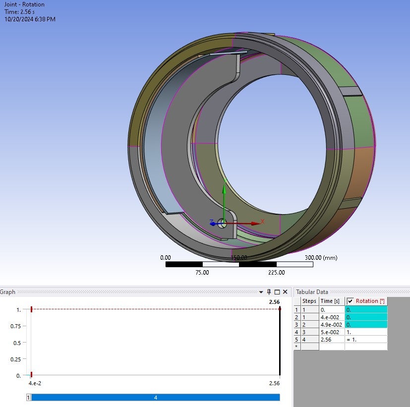
A joint rotation is also defined but it is suppressed for now-
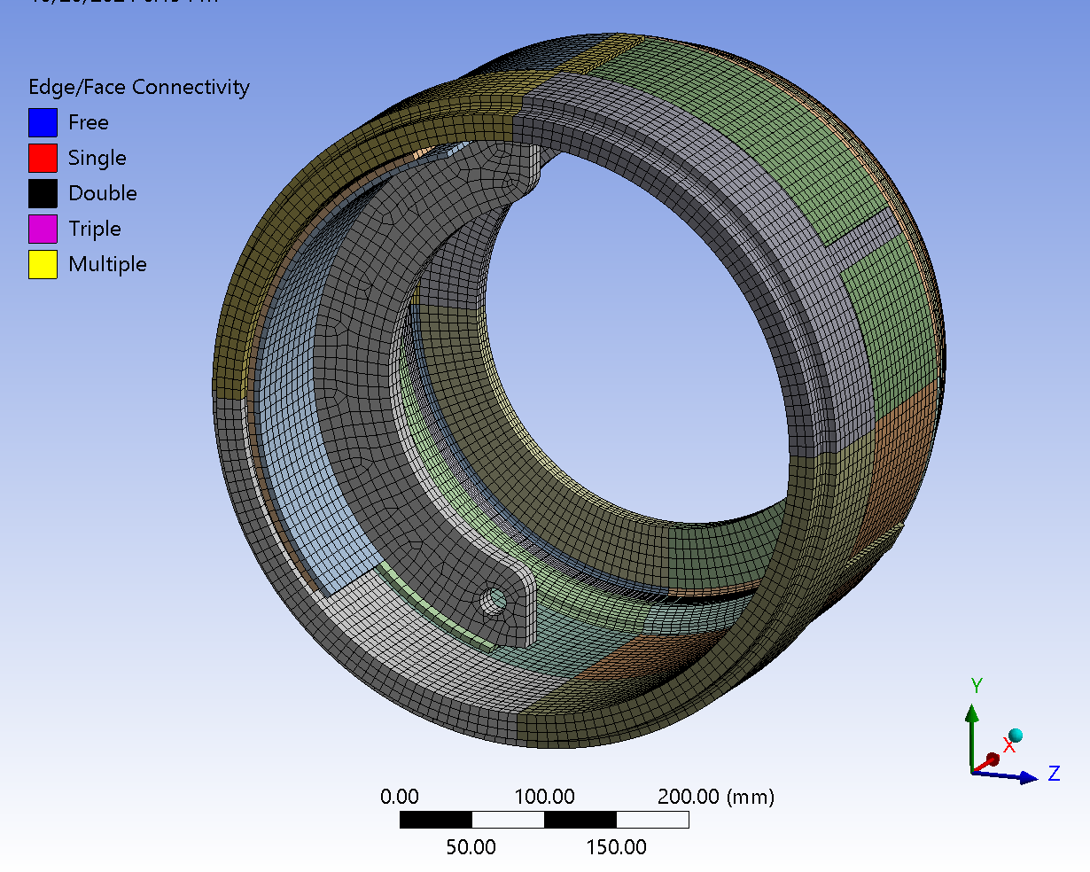
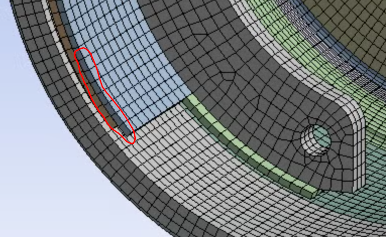
A snapshot of mesh is given below,
I had not shared the details of the time step settings previously, so I've attached the screenshot of the timesteps below,
Please let me know if any corrections need to be made in any of the connections, loads, BCs, mesh, etc. Looking forward to your reply.
Regards,
Rohan.
-
October 20, 2024 at 8:31 pm
peteroznewman
SubscriberRegarding the mesh on the shoe, one solid quadratic element through the thickness is generally insufficient to capture the stress due to bending of the material. A minimum of two solid quadriatic elements should be used.
Brakes get hot from the friction, normal force, and surface velocity integrated over time between the brakepad and the brakedrum. Is your model generating heat by this method? Heat would be conducted away from the surface the pad slides on to the rest of the drum and convection cooling could transfer the heat to the ambient air.
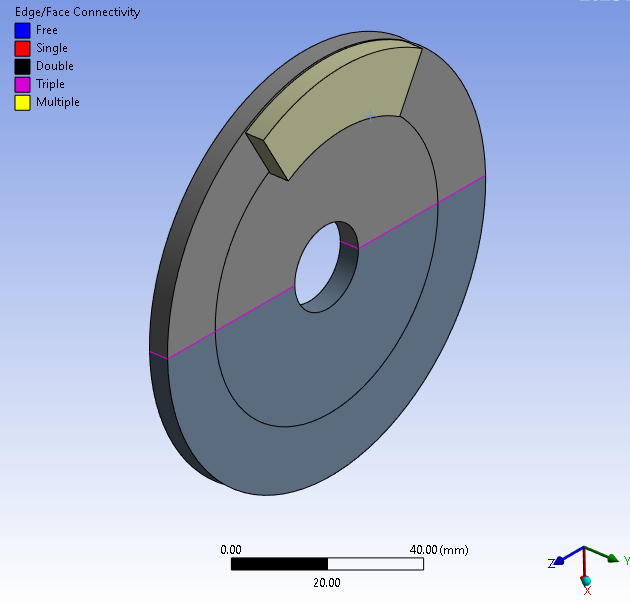
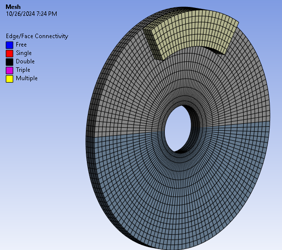
I advise you to make a very simple two body model of a disc plate with a center hole. Mesh the disc with 4 elements through the thickness and a small pad of equal thickness on the top of the disc positioned so it is near the outer diameter of the disc.
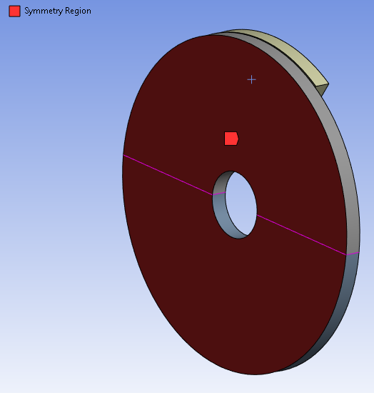
Make it a symmetric model so that you only have a half-thickness disc. The symmetry boundary conditions will keep the disc from bending, it will be as if there is a pad on the other side pushing up. Put a revolute joint on the face of the hole in the disc and use a rotational load to rotate the disc. Mesh the pad with 4 elements through the thickness. Put a translational joint to ground on the top of the pad. Add a Joint Load of Force to press the pad into the disc. Frictional contact between the pad and disc will create the heat source along with the rotation and the normal force. In a Transient Structural model, you should be able to see the disc and pad warm up over time. You don’t need any other heat transfer boundary conditions. First step is to show a temperature result that is higher than the 20C initial temperature.
Good luck!
-
October 21, 2024 at 3:44 am
engr.rohan7
SubscriberHello Peter,
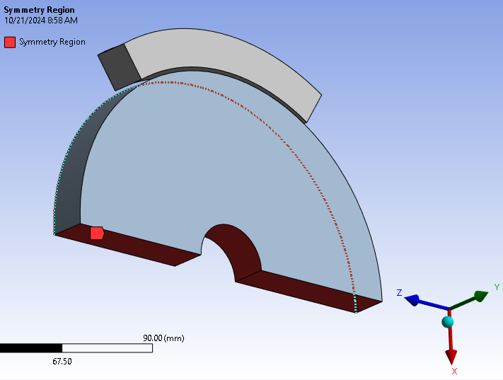
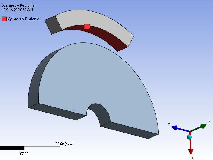
As you mentioned I've created a symmetry region as specified shown below,
Disc-
Pad-
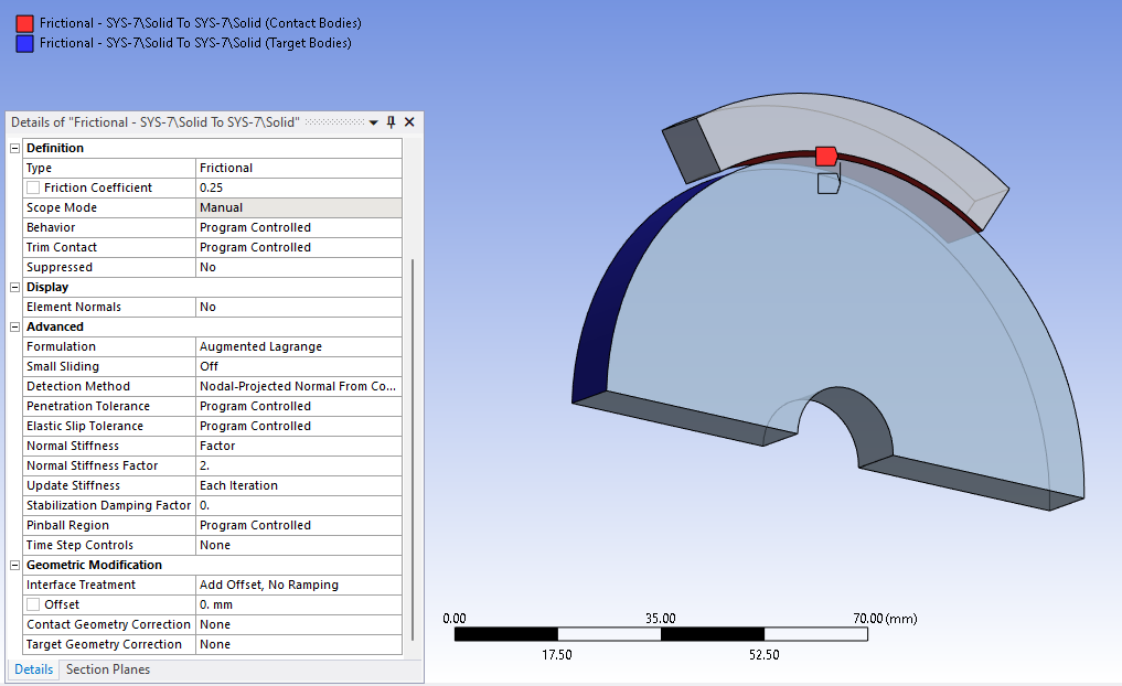
Contacts are as follows,
Frictional-
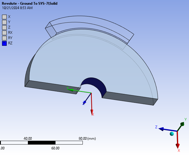
Joints are shown below,
Revolute-
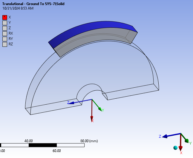
Translational-
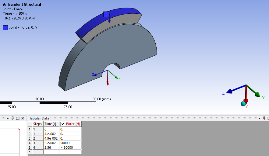
Joint Force load is defined-
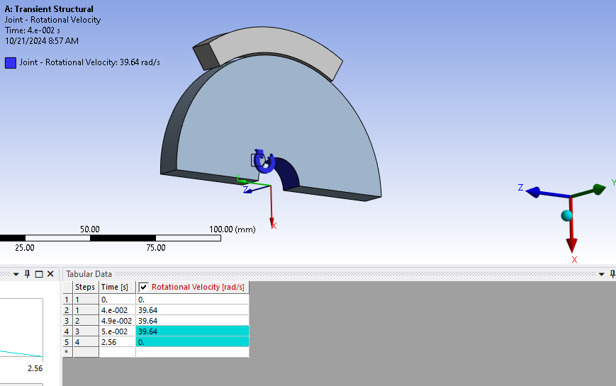
Joint rotational velocity is given-
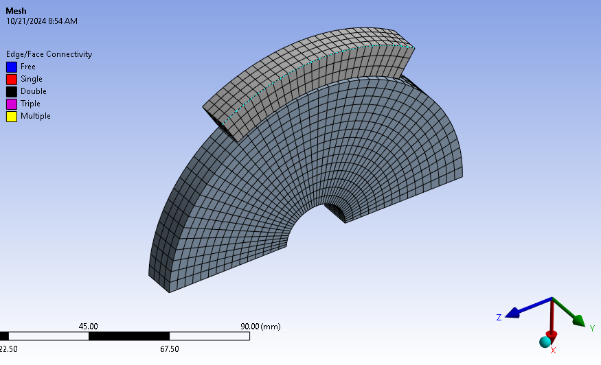
Mesh is generated using 2nd order elements-
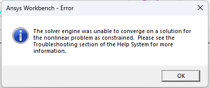
However, after running the simulation I'm getting error and solution isn't converging-
I would like to know whether the model is generated as per your suggestions and if not, would like to know changes needed to be made.
Regards,
Rohan.
-
October 21, 2024 at 11:05 am
-
October 26, 2024 at 3:09 pm
engr.rohan7
SubscriberHello Peter,
I had previously made the geometry from drum brake context. I’ve recreated the model as you mentioned shown below,
Mesh with 4 elements across thickness-
Symmetry region created. Any corrections required here?
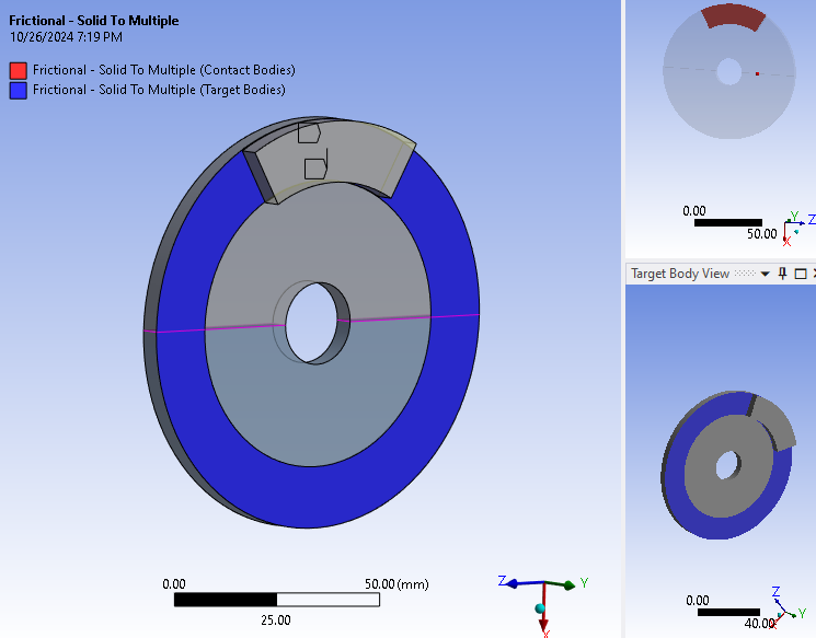
Frictional contact given-
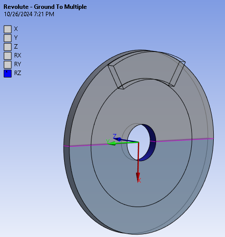
Revolute joint-
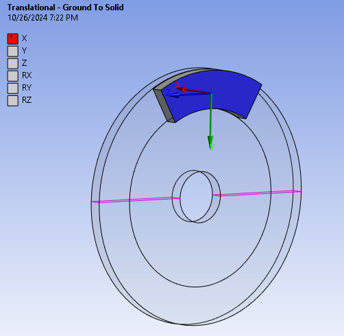
Translational joint-
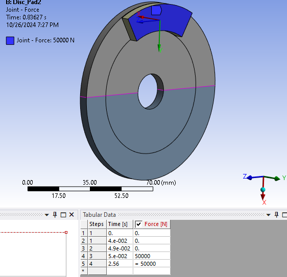
Joint loads- Force & Rot. Vel.-
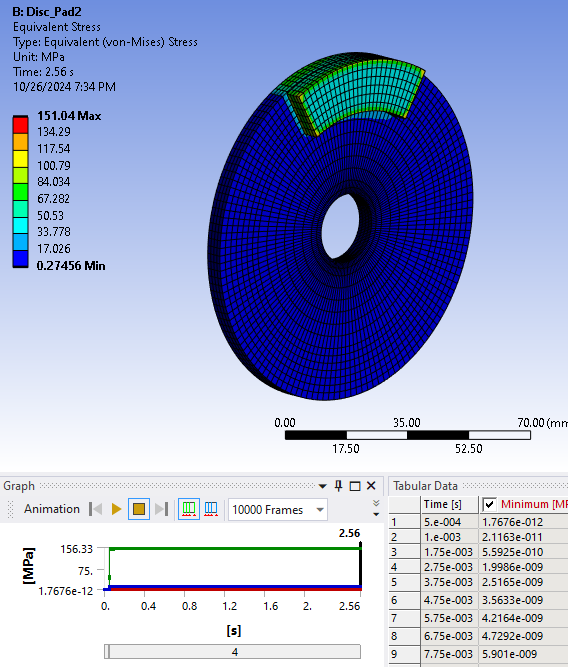
Equivalent Stress- Max. occurs in pad-
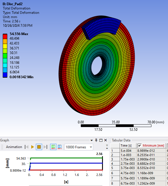
Total deformation- Max occurs in disc-
The stress and deformation is seen to be constant after joint force application.
In one of your previous posts, you had mentioned the method to apply the rotational velocity as joint load the link is mentioned below-
https://www.google.com/url?sa=t&source=web&rct=j&opi=89978449&url=https://innovationspace.ansys.com/forum/forums/topic/initial-angular-velocity-in-transient-structural/&ved=2ahUKEwi1-fj-o6yJAxWRT2wGHTR5KG0QFnoECCQQAQ&usg=AOvVaw0eMNi-CudqpMyj76-OaYio
I’ve followed the steps mentioned in the above post and applied the joint load rot. vel. so as to get a free rotation at 0.05s , but I don’t see the disc gradually coming to a stop at the end of 2.56s when brake force is applied at 0.05s. In the above image for rotational velocity, I’ve deactivated the steps for 0.05s and 2.56s in order to get a free rotation. Should I make any changes to the applied load?
I am trying to achieve that free rotation, but after brake force at 0.05s, the disc stops suddenly. I've observed this same case while performing the coupled field transient for brakedrum mentioned in the previous discussion.
I would like to know your suggestions regarding how I can use this simulation physics of disc brake and implement it for drum brake simulation.
Regards,
Rohan.
-
October 26, 2024 at 9:51 pm
peteroznewman
SubscriberThis looks mostly fine Rohan, the disc stops suddenly because it has a very small inertia.
One suggestion is to have two separate materials for the disc and the pad. Edit the density of the material for the disc and add 3 zeros to the value so it is 1000 times heavier. If necessary, you can add another zero or two.
You didn't follow the times I laid out in the other discussion which I have copied below.
- Step 1, ramp the Rotational Velocity from 0 to the desired value in 0.9 seconds.
- Step 2, hold the Rotational Velocity constant for 0.09 seconds.
- Step 3, Deactivate the Joint Load (unless you want it active) in 0.01 seconds.
- Step 4, Apply the brakes!
- All your braking data will start at t=1.00 seconds.
You are ramping up the rotational velocity in 0.04 seconds. That will cause a large stress in the massive disc.
When you apply the brakes, you are ramping the force on over 0.01 seconds. Ramp the force on over 0.1 seconds.
-
October 28, 2024 at 6:19 pm
engr.rohan7
SubscriberHello Peter,
I have a doubt regarding the 4 steps mentioned above regarding application of rotational velocity as joint load. Since we are dealing with deceleration due to braking, initial condition will be, at t= 0s, rotational velocity is x rad/s, and after braking at t= 2.5s rotational velocity is 0.
Why can’t we take the actual rotational velocity at t= 0s instead of ramping from 0 to given rotational velocity through a span of say 0.1s?
Regards
Rohan.
-
October 29, 2024 at 12:28 am
peteroznewman
SubscriberHello Rohan,
You would think you could just type in 36 rad/s as an initial condition for the rotational velocity at t=0 within Mechanical. I have done that with other software.
You can do that using an APDL Command Object. Use the command ICROTATE to apply OMEGA to a list of nodes on the disc and provide two points to define the rotation axis.
If you want to avoid using APDL, then you need to use a multistep approach. A more efficient set of steps than the one in my previous reply requires turning Time Integration Off and On.
- Step 1, turn off Time Integration, use a Joint Displacement of 0.0036 radians and an end time of 0.0001 seconds. That creates a 36 rad/s rotational velocity. Since Time Integration is off, this massive acceleration causes no stress.
- Step 2, Deactivate the Joint Load so the revolute can spin freely, turn on Time Integration so the brakes can be applied in the next step, use an End Time of 0.0002 seconds.
- Step 3, Ramp up the Brake force with an end time of 0.1 s
- Step 4, Keep the Brake force Constant with an end time of 1 s. The disc will stop somewhere between t=0 and t=1.
Check the rotational velocity to make sure the model attained the desired rotational velocity.
-
November 15, 2024 at 6:19 am
engr.rohan7
SubscriberHello Peter,
As per your suggestions, I applied the loadsteps with time integration turned off for first step.
After running the simulation, following are the results,
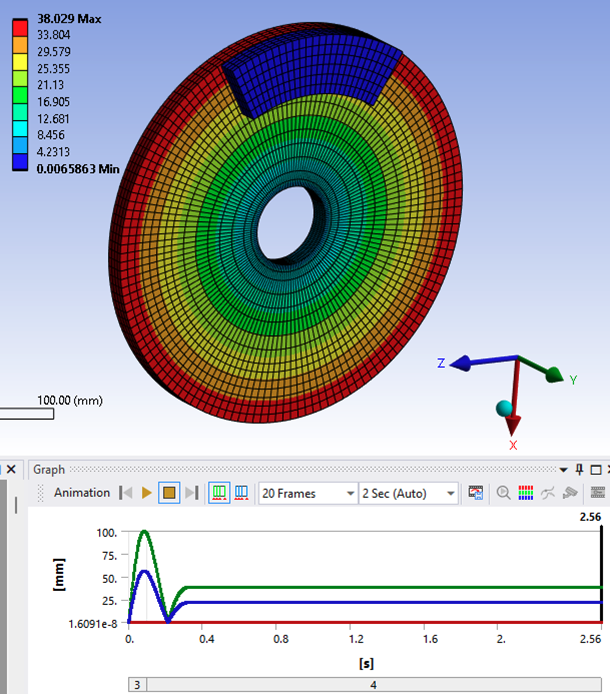
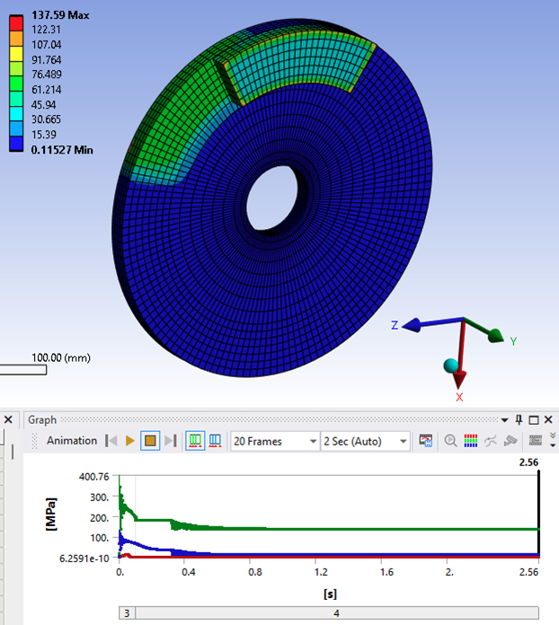
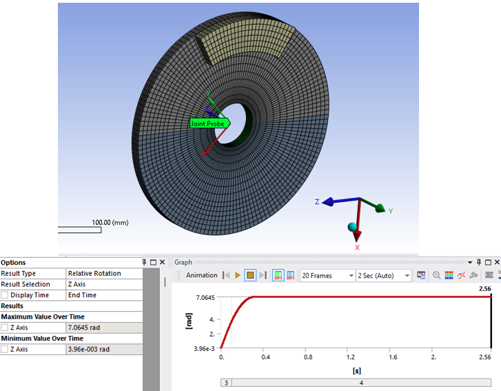
Total deformation-The disc appears to be expanding for total deformation and joint probe (relative rotation).
Equivalent stress as shown below-
Joint probe as shown below-
This result is obtained for modified density after multiplying by a factor of 1000.
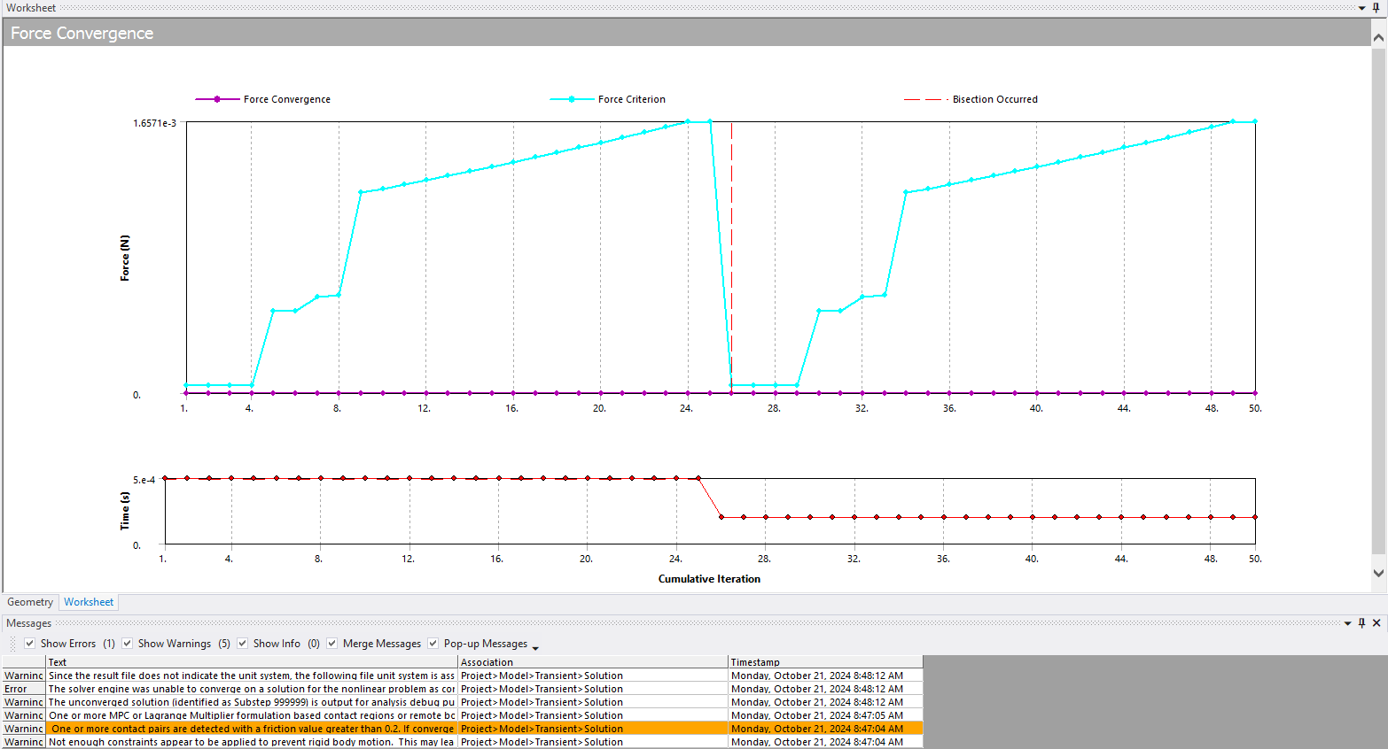
I've also tried a coupled field transient for this disc brake. I have kept time integration off for the first load step.
I have got a list of messages after the run as follows-
I am getting an error as follows-
The error is as follows as per solution output-
*** ERROR *** CP = 2216.203 TIME= 00:00:33
Solution not converged at time 1.E-04 (load step 1 substep 1).
Run terminated.Before the above error, a warning is seen as follows-
Contact element 20199 (real ID 6) status changes abruptly from contact
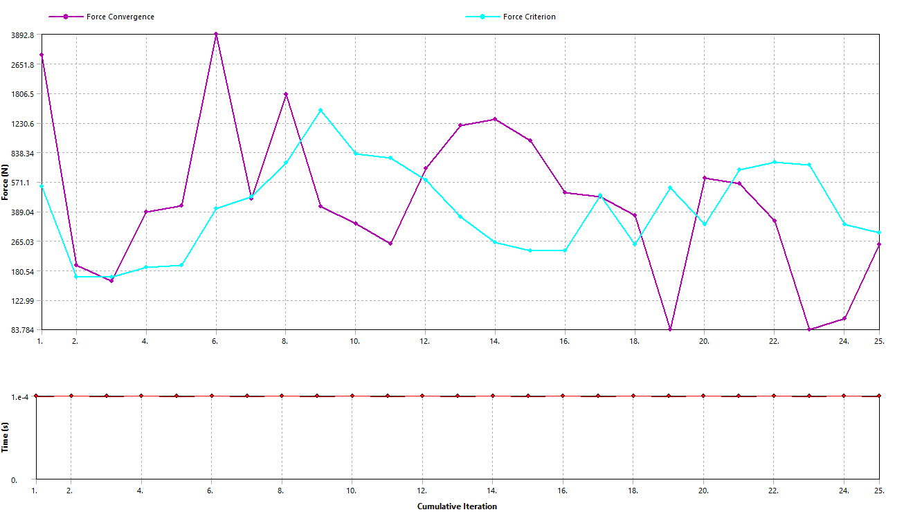
(with target element 21278) -> no-contact.The force convergence plot does not show the substeps converged,
Two physics region have been defined as follows-
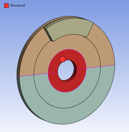
Structural-
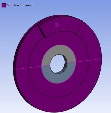
Structural- Thermal -
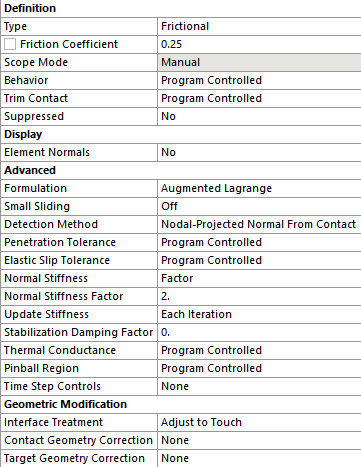
The frictional contact details are as follows-
I have also applied command snippets as follows-
Frictional contact-
Transient analysis-
Any suggestions for resolving these issues?
Another point, I would like to know how to get a temperature distribution in transient structural due to frictional braking?
As you mentioned, after increasing the density I could observe the rotational velocity increasing in the first load step after turning off time integration. So thank you for that suggestion.
Looking forward to your reply,
Regards,
Rohan.
-
November 20, 2024 at 1:49 am
engr.rohan7
SubscriberHello Peter,
As per your suggestions, I applied the loadsteps with time integration turned off for first step.
After running the simulation, following are the results,
Total deformation-The disc appears to be expanding for total deformation and joint probe (relative rotation).
Equivalent stress as shown below-
Joint probe as shown below-
This result is obtained for modified density after multiplying by a factor of 1000.
I've also tried a coupled field transient for this disc brake. I have kept time integration off for the first load step.
I have got a list of messages after the run as follows-
I am getting an error as follows-
The error is as follows as per solution output-
*** ERROR *** CP = 2216.203 TIME= 00:00:33
Solution not converged at time 1.E-04 (load step 1 substep 1).
Run terminated.Before the above error, a warning is seen as follows-
Contact element 20199 (real ID 6) status changes abruptly from contact
(with target element 21278) -> no-contact.The force convergence plot does not show the substeps converged,
Two physics region have been defined as follows-
Structural-
Structural- Thermal -
The frictional contact details are as follows-
I have also applied command snippets as follows-
Frictional contact-
Transient analysis-
Any suggestions for resolving these issues?
Another point, I would like to know how to get a temperature distribution in transient structural due to frictional braking?
As you mentioned, after increasing the density I could observe the rotational velocity increasing in the first load step after turning off time integration. So thank you for that suggestion.
Looking forward to your reply,
Regards,
Rohan.
-
-
November 20, 2024 at 12:13 pm
peteroznewman
SubscriberHello Rohan,
Sorry for the delay in my reply, I only participate here when I have free time and I have not had much of that in the last few weeks.
I would like to get a copy of your model to study further. Please use File, Archive in Workbench to save a .wbpz file without results and upload that to cloud storage such as Google Drive, OneDrive or Jumpshare. Then paste the link to that file in your reply.
Another suggestion is to create a New Discussion and paste an edited version of this last reply that narrowly targets the question: How to get heat generation from the frictional contact and sliding and see the resultant temperature rise. I won't reply in that thread and hope that someone who can help will reply. This discussion is over a dozen replies and many people will not read through all the replies to get to the last question in the thread.
Regards,
Peter
-
November 22, 2024 at 7:27 pm
engr.rohan7
SubscriberHello Peter,
Thank you for providing your insights and resolving my doubts. Your guidance and suggestions have helped me resolve many queries regarding brakedrum FEA and I am thankful for that.
Below is the link for the archive file.
https://drive.google.com/file/d/1kVuh_tnMQ-FukeDynqj_4ysCq71o2VYs/view?usp=sharing
As suggested, I will create a new discussion for this topic.
If you need anything from my side do let me know.
Regards,
Rohan.
-
- You must be logged in to reply to this topic.


-
5094
-
1829
-
1387
-
1248
-
1021

© 2026 Copyright ANSYS, Inc. All rights reserved.

