-
-
November 28, 2024 at 10:31 am
sriparna.2021rce15
SubscriberI am trying to model PZT patch (10mm x 10mm x 0.3mm) bonded on a beam (700mm x 150mm x 150mm) and perform coupled field harmonic analysis in order to obtain impedance (impedance vs frequency plot) The help manual for the: Mechanical Technology Showcase: Example Problems Chapter 39: Wire Bonding Ultrasonic Transducer states that the degree of freedom needs to be coupled as shown in fig.
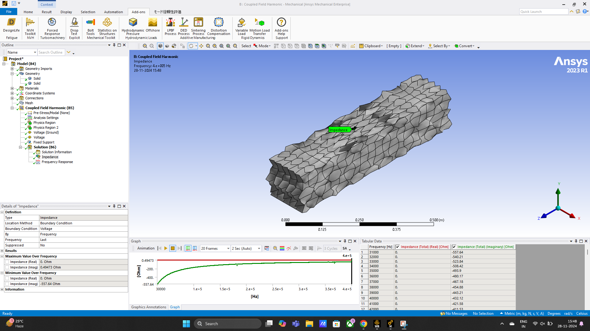
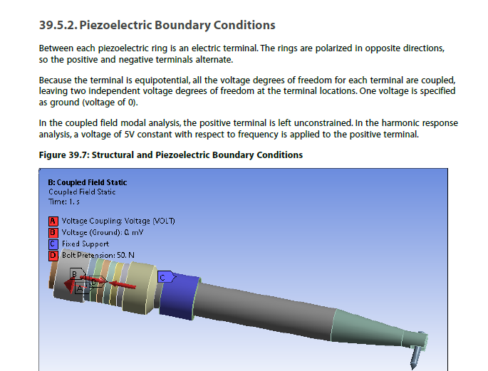 So I tried to couple the bottom face of pzt patch (bottom voltage coupling) and top face of the PZT patch was coupled (tom voltage coupling). Then 0 Volt (voltage ground) is applied at the bottom face of the pzt patch and 1 Volt (voltage) at the top face of the pzt patch. The physics region provided in model is as follows:
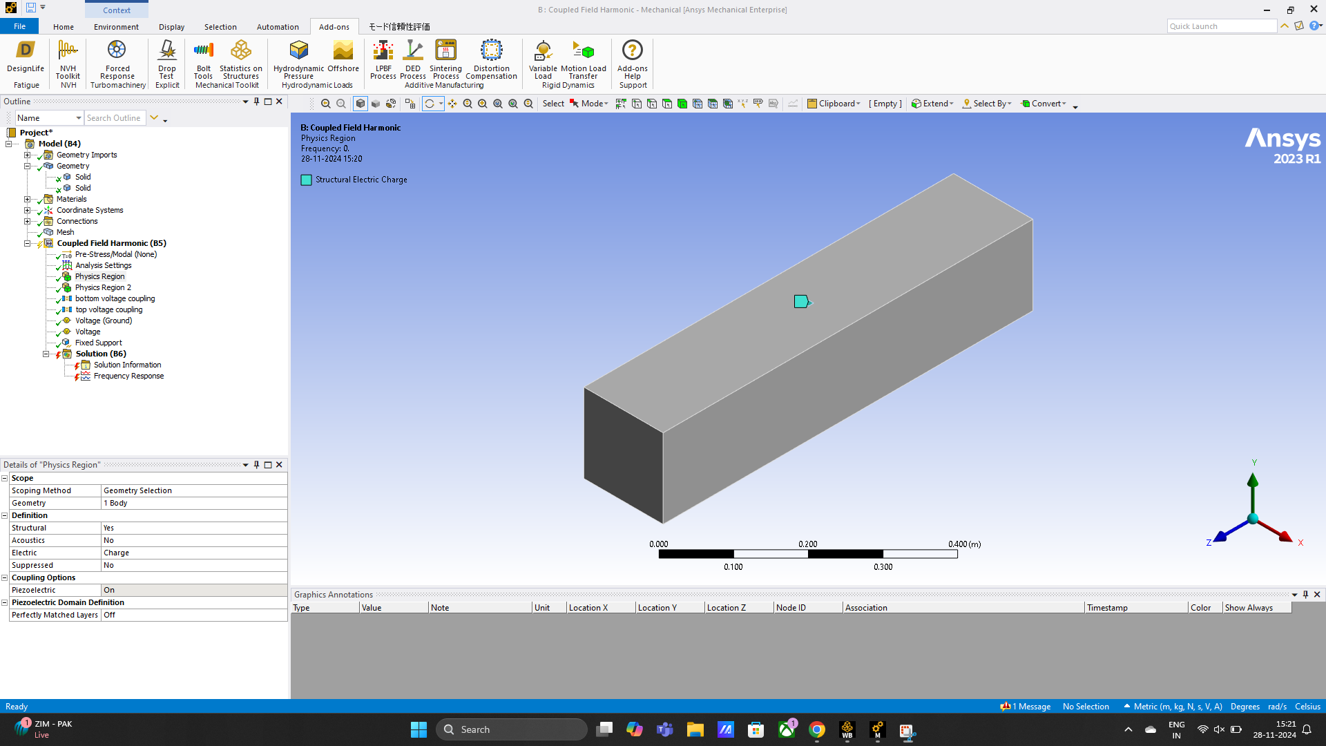
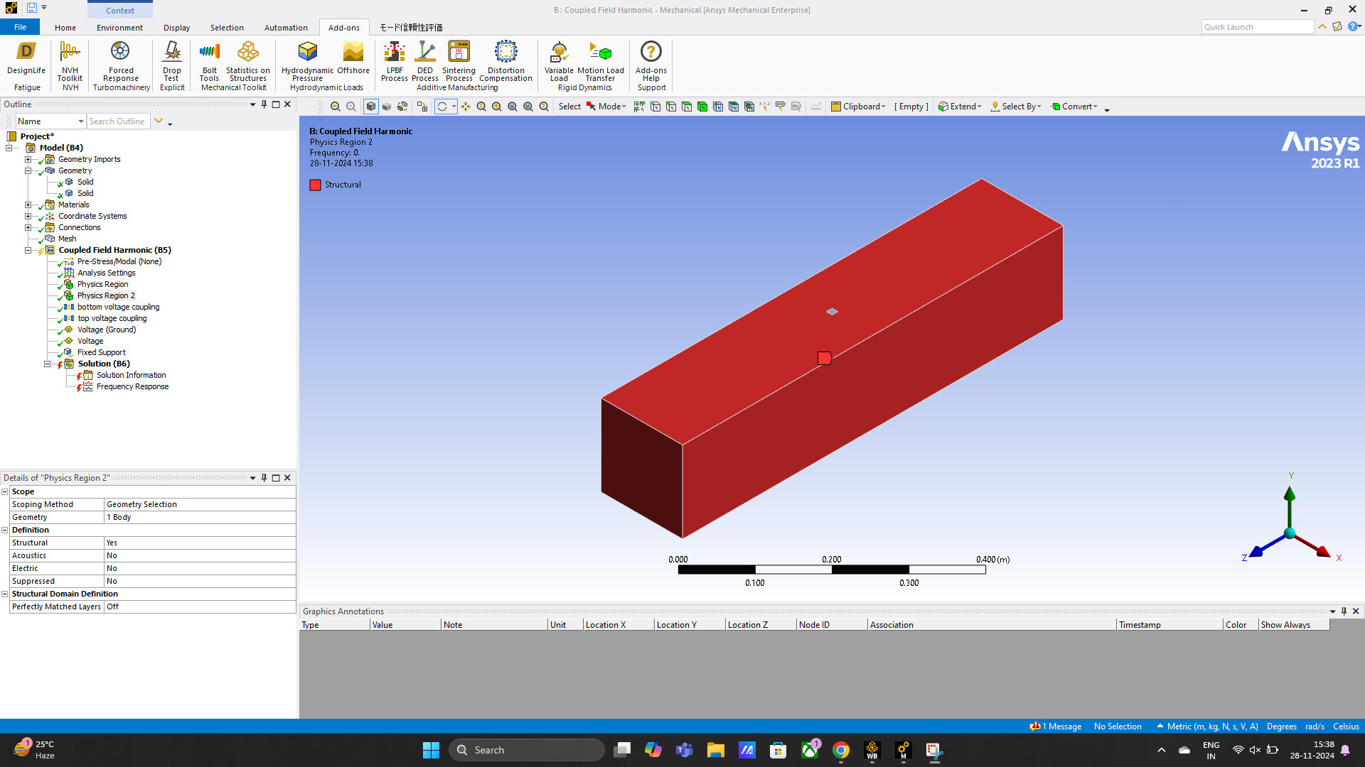 The model was executed, but following error came up.
 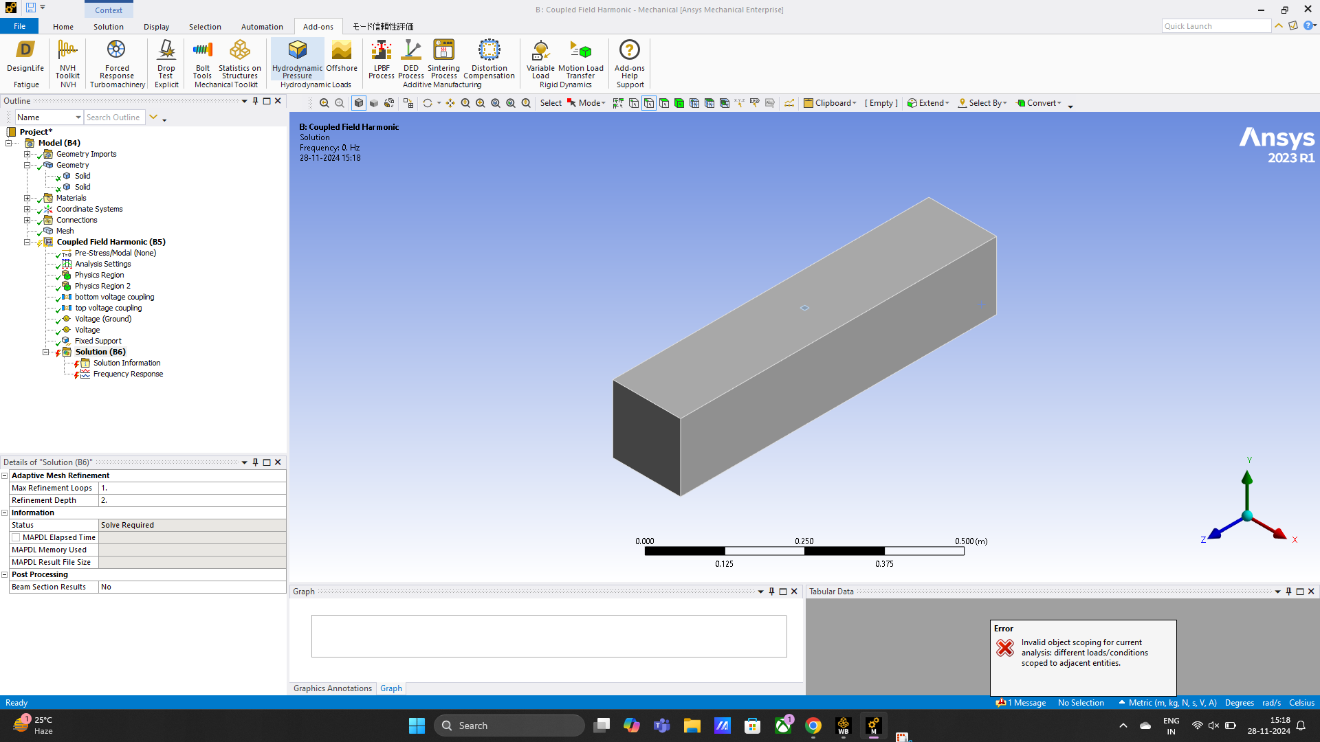 In order to solve the analysis successfully, I tried removing the coupling and the analysis was performed. The results were as shown in below figure. According to me, I feel these results are not correct. Kindly tell me what I have done wrong so that I could get proper results of impedance.
-
November 30, 2024 at 5:10 pm
dlooman
Ansys EmployeeThe set up you describe with coupling the top and bottom faces and setting one to 0 volt (ground) and the other to 1 volt seems correct. It's not possible to read the error message. Could you provide the text of the message?
-
November 30, 2024 at 5:26 pm
sriparna.2021rce15
SubscriberError is as follows: Invalid object scoping for current analysis: different load/conditions scoped to adjacent entities
Not applying coupling is ok?
-
December 2, 2024 at 4:53 pm
dlooman
Ansys EmployeeYes, you don't need to couple volt. You can just specify the voltage on the faces without coupling it. Usually coupling is used for postprocessing purposes, but it's totally optional.
-
- You must be logged in to reply to this topic.


-
4673
-
1565
-
1386
-
1231
-
1021

© 2025 Copyright ANSYS, Inc. All rights reserved.


