
TAGGED: bearing, mechanical, rigid
-
-
March 4, 2022 at 1:56 pm
stevenfarm
SubscriberMarch 4, 2022 at 9:53 pmpeteroznewman
Subscriber In the future, please post your images into your discussion using the Image button rather than attaching a file. ANSYS employees are not permitted to download attachments.
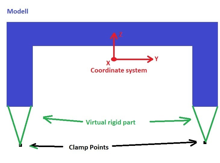
In ANSYS Mechanical, in a Static Structural analysis, there is a Support called Remote Displacement. Select the face at the base of one leg and click Remote Displacement. There are 6 DOF where you can enter 0 to fix 3 translations and 3 rotations. The point will automatically have been placed at the center of the selected face, so in the Details window, type in new X, Y, Z coordinates for location of the Remote Point. Finally, there is a line item called Behavior. By default is it Deformable, change that to Rigid. Repeat on the other leg.
You said you only want to constrain translations in X, Y and Z at the clamp points. For a 3D model, that is not enough constraints to prevent rigid body motion. The structure will be able to spin around the two points. If you have 3 or more non-collinear points, you can prevent the spinning. Or you can apply a zero rotation at one or both of the two clamp points.
Viewing 1 reply thread- The topic ‘Correct way of bearing (Rigid Virtual Part)’ is closed to new replies.
Innovation Space Trending discussions
 Top Contributors
-
peteroznewman
 5884
5884 -
scabo
 1906
1906 -
Dennis Chen
 1420
1420 -
javat33489
 1306
1306 -
Shyam Prasad V Atri
1021
Top Rated Tags
© 2026 Copyright ANSYS, Inc. All rights reserved.
Ansys does not support the usage of unauthorized Ansys software. Please visit www.ansys.com to obtain an official distribution.
-


The Ansys Learning Forum is a public forum. You are prohibited from providing (i) information that is confidential to You, your employer, or any third party, (ii) Personal Data or individually identifiable health information, (iii) any information that is U.S. Government Classified, Controlled Unclassified Information, International Traffic in Arms Regulators (ITAR) or Export Administration Regulators (EAR) controlled or otherwise have been determined by the United States Government or by a foreign government to require protection against unauthorized disclosure for reasons of national security, or (iv) topics or information restricted by the People's Republic of China data protection and privacy laws.
