TAGGED: beam, mechanical, Screw
-
-
September 21, 2023 at 9:36 am
camilla.gironi4
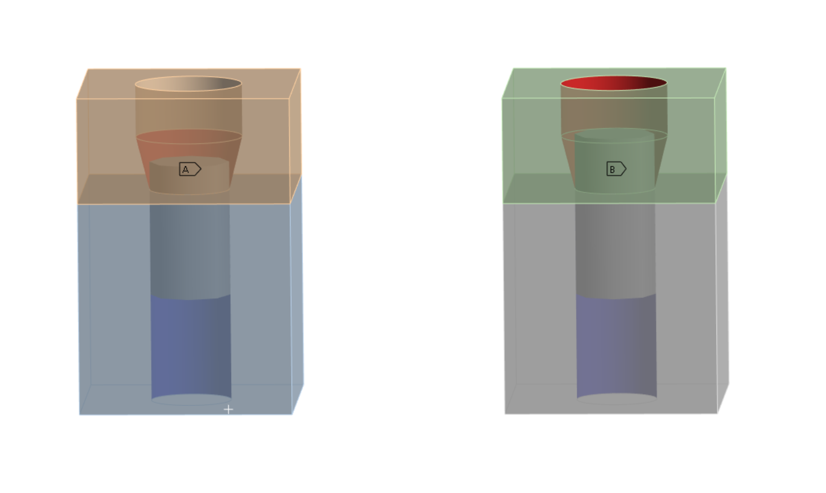
SubscriberHi everyone, I'm simulating in Static Structural the presence of a screw between two objects with a beam connection. I followed some tutorials I found on the Innovation Space but I'm still not sure about its correct modelling. My doubt is regarding the Reference surface to use. I tried the two configurations in the attached image: on the left (case A) I selected only the bottom surface of the hole in the reference body (in red), while on the right (case B) I selected both the top and bottom surface of the hole in the reference body (in red).
Do you have any explanation about the difference between the two setups? Which one is the correct one?
-
September 25, 2023 at 9:51 am
Aniket
Forum ModeratorIt will depend on how the actual bolt is modeled, but most likely it will be the one on left, as no bolt can exert pressure on vertical cylindrical wall when tightened.
-Aniket
-
September 25, 2023 at 10:51 am
camilla.gironi4
SubscriberThank you for your suggestion.
In the case I use the first setup (the one on the left), how can I model the interaction of the "vertical cylindrical wall" with the top object? Since in reality, there is screw material interacting with the object even if it does not contribute to bolt pretension
Thank you again,
Camilla
-
-
September 25, 2023 at 12:24 pm
Zoi Stavrothanasi
Ansys EmployeeHello Camilla,
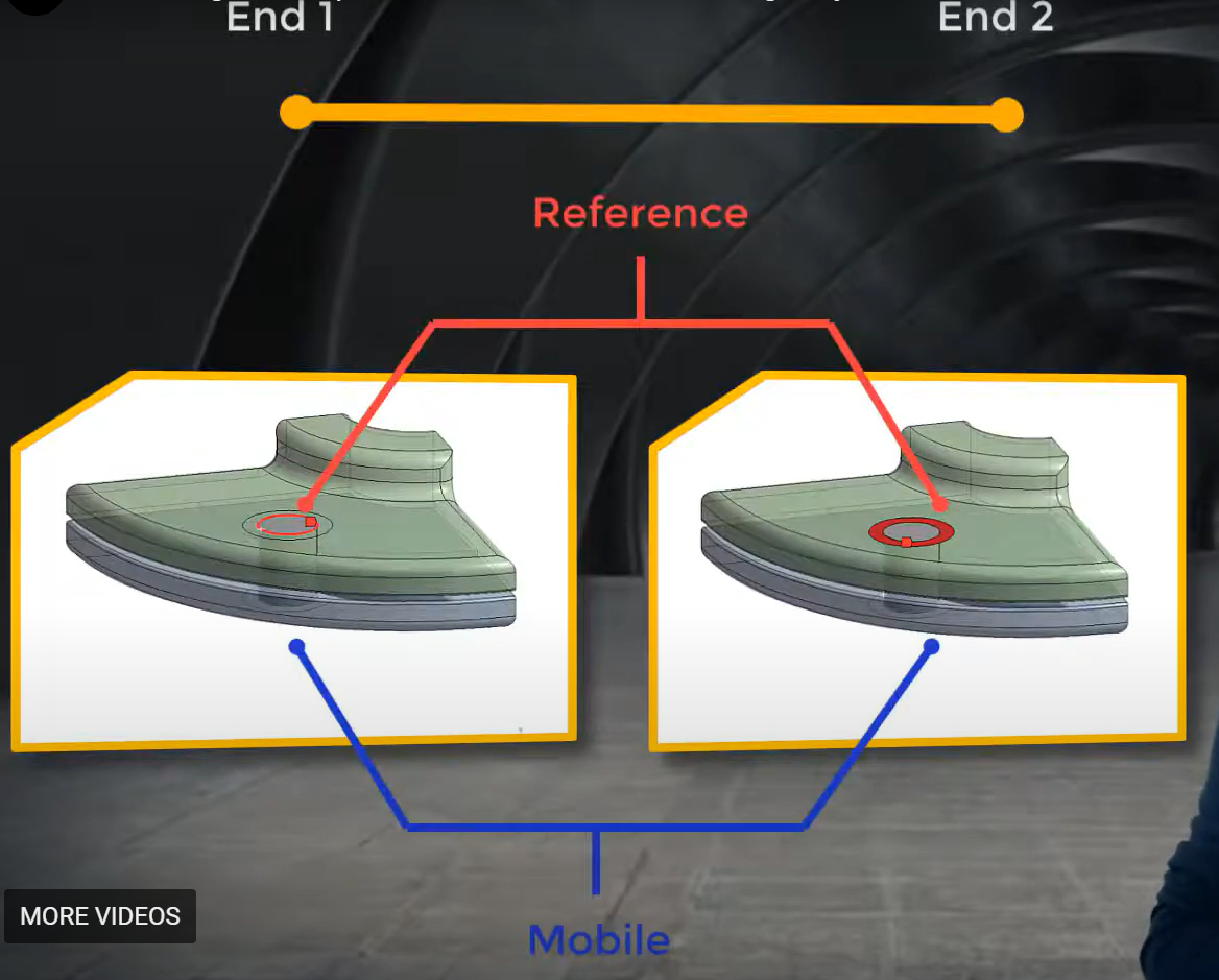
When using beam connections you have to define the two ends of the beam, which are represented by the referenece and the mobile. You can choose betwwen a face to face connection and an edge to edge connection:
Please review: Connecting bolts represented as beam elements for further details. Also note that the use of beam connection is suggested when the user is interested in bolt load history of an assembly an not in the results near the bolt hole. Hope this helps!
Regards,
Zoi
-
- The topic ‘Correct beam connection to simulate screw’ is closed to new replies.


-
4904
-
1598
-
1386
-
1242
-
1021

© 2026 Copyright ANSYS, Inc. All rights reserved.


