-
-
May 20, 2024 at 10:36 pm
aqbaich
SubscriberHello team
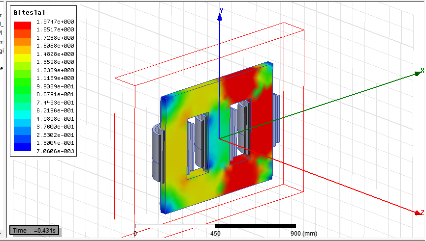
i am tryong to simulate the no load losses test of 400kva 20kv 400V in Ansys maxwell. the aim is to predict the value of core losses and the distribution of magnetic fields in the core. in the factory, we apply the voltage in scondary side (400v) . the HV side of corse is open.
to explore the symetry of the activ part , i used a half model as shown in next figure :
because of symetry , i applied half voltage as excitation in winding :
phase A=115*cos(2*pi*time), Phase B=115*cos(2*pi*time+2*pi/3) phase C=115*cos(2*pi*time+4*pi/3)1:
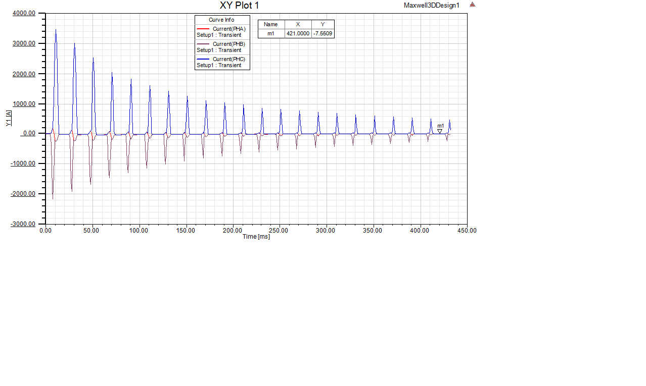
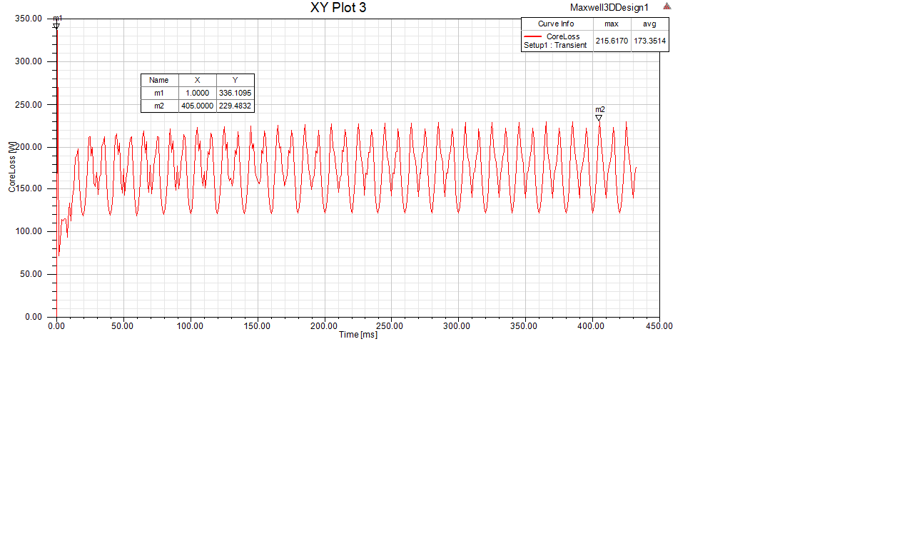
i expect to find an the max value of magnetic filed 1.78T and the core losses around the half mesured =450w ( 900w in mesured corlosses of total active part and the current in winding should be very low . unfortunatly, i find the core losses around 236w , the max od magnetic field around 1.94T and winding current started with a huge value od 3.5KA as shown below . can you please help me to undertsund where is the mistake
-
May 21, 2024 at 2:14 pm
GLUO
Ansys EmployeeHi,
Voltage excitation requires correct winding resistance value. If symmetry multiplier is used, the voltage applied should be the voltage for the full winding. The open circuit winding needs to be assigned with 0 current excitation.
GL
-
May 21, 2024 at 2:58 pm
aqbaich
SubscriberThank you for your feed back . In fact, for winding resistance , i have taken the value mesured wich is 2,7 mΩ and i divised by 2 when assigning the value of resistance in ansys because i used the half winding.
i didn't use the symetry multiplier because i designed the half model in Solidworks and import it to ansys maxwell
-
- The topic ‘CORE LOSSES IN 3 PHASE TRANSFORMERS’ is closed to new replies.


-
5089
-
1823
-
1387
-
1248
-
1021

© 2026 Copyright ANSYS, Inc. All rights reserved.


