-
-
December 11, 2018 at 10:50 am
superduke1200
Subscriber
Dear members,
I am implementing a fluid analysis on cerebral aneurysms and it is obligatory to apply the origin of my coordinate system at the inlet of the aneurysm.
I use Ansys Mechanical for the meshing of my geometry and as you know it comes with a pre-applied Global coordinate system. I am able to create a new coordinate system at the inlet of the aneurysm ( 2nd Image ), but my query is as follows;
how can I use my 'Custom' coordinate system applied on the Inlet as the default one instead of the global?
You see, after I have created my mesh, I am using Ansys Fluent and I must use the 'Custom' coordinate system in order to have accurate results when I calculate coordinate related factors.
Fluent uses the Global one, created by default in Mechanical. I have already tried the 'Translate Mesh' option ( 1st Image) based on the offsets derived from Mechanical, but it is not enough, because an alignment of the axes-Mesh is required. And the 'rotate mesh' option is not adequate to create a correlation from the data provided in Mechanical. I guess that's it.
I hope you will find time some day and share your thoughts with me.
-
December 11, 2018 at 12:28 pm
superduke1200
SubscriberPost edited in correct format
-
December 11, 2018 at 2:53 pm
Keyur Kanade
Ansys Employeeyou can use translate and rotate in fluent.
there is no direct command for local coordinate system in fluent.
is there any specific reason you want local coordinate?
-
December 11, 2018 at 3:37 pm
superduke1200
SubscriberThank you for your response.
I am familiar with the translate and rotate options in Fluent.
The reason why I want to place a coordinate system at the inlet of my aneurysm is because I have a UDF file of the velocity profile which looks like this.
This means that there should be a velocity component ( suppose Z axis ) which will point inwards the aneurysm and starting from the Inlet. In other words, it should indicate the direction of the blood flow.
Otherwise, any critical parameters regarding aneurysm rupture, like Wall Shear Stress or Pressure will not have the appropriate values if we use the Global coordinate system located at a random position. At least that is what I consider as logical.
Using the Translate Mesh option allows me to transfer the mesh where I wish, but not rotated like I do. The result would be something like that
A mesh where I want it to be but not rotated correctly.
We can find out the Translation which I am talking about using Mechanical, as pictured below
Unfortunately, Mechanical does not provide any Rotation correlated information in order to use them in the Rotate Mesh option of Fluent.
For the record, I am able to create a Mesh using the same Geometry file utilising ICEM CFD
And then create a coordinate system at the Inlet which will be used as Default when I am running Fluent. Problem solved? No.
Unfortunately, ICEM generates linear elements by default and does NOT support quadratic elements with midside nodes like Mechanical does.
The problem is that midside nodes are necessary to predict proper stresses like I need in my occasion, which makes the use of ICEM inappropriate.
Any suggestions are more than welcome.
-
December 11, 2018 at 5:01 pm
Rob
Forum ModeratorIf the flow is perpendicular to the boundary then use Magnitude normal to boundary. Otherwise, use the coordinates you have to recalculate the vector and use that along with the magnitude. Both options are under the velocity boundary in Fluent.
We do have local coordinates for fluid regions to determine swirl numbers etc, but they're not appropriate in this scenario.
-
December 11, 2018 at 7:15 pm
superduke1200
SubscriberThe flow is perpendicular to the boundary, yes.
I always use the Magnitude normal to boundary option. Now here is an interesting result.
In the case that I described earlier, if I use the global coordinate system generated my Mechanical, WSS (Wall Shear Stress) has a magnitude of 206 Pa at the wall of the aneurysm.
In the same case, when I apply the Translate Mesh option ( i.e a translation at the Y and Z direction in the order of meters, for a mesh whose diameter is 0.002meters) in order to transfer (not rotate) the mesh based on the Mechanical data that I derived from Mechanical
the WSS is 297.000 Pa
Both cases have the Magnitude normal to boundary option applied and for the shake of simplicity, a constant inlet velocity of 0.5m/s.
But the difference in WSS is almost 1000%! This leads me to the suspicion that the origin of the Coordinate system has a great impact on the outcome. If it did not I assume that opting for the Magnitude normal to boundary option would be enough.
I am not pretty confident that I understand;
use the coordinates you have to recalculate the vector and use that along with the magnitude
I guess I can find the section that you suggest
but I cannot figure out the rest based on the data that I have.
-
December 11, 2018 at 7:32 pm
Amine Ben Hadj Ali
Ansys EmployeeHow are you evaluating the shear stress in Fluent?
-
December 11, 2018 at 7:50 pm
superduke1200
SubscriberYou can find it in Fluent as follows
Here is the way to calculate the WSS
-
December 11, 2018 at 7:54 pm
Amine Ben Hadj Ali
Ansys EmployeeDoes it mean you are just looking into the contour plot of wall shear stress at the wall?
-
December 11, 2018 at 7:55 pm
superduke1200
SubscriberYes
-
December 11, 2018 at 8:16 pm
Amine Ben Hadj Ali
Ansys Employee1/Check if the area of the wall has changed in Fluent?
2/Which boundary conditions and Models are you using in Fluent? Is it the same case you are looking into it? What happens if you run the case and then apply any translation meanwhile reporting max and area average of wall shear: do the monitors change?
-
December 12, 2018 at 10:09 am
Rob
Forum ModeratorCan you compare surface average shear stress (under Reports): all it takes is one cell to change angle to give a large change in the maximum value and this could also be an anomaly caused by skew mesh.
The vector in the second panel is only needed if the flow is not perpendicular to the surface: you'd need to use 3d trigonometry so stick with magnitude normal to surface!
-
December 12, 2018 at 3:07 pm
superduke1200
Subscriber
1) Wall area in Mechanical; 0.001669.8 m2
Wall area in Fluent; 0.001670.4 m2
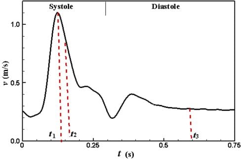
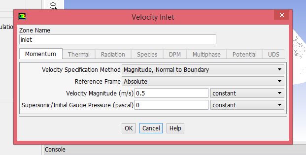
2) Boundary conditions; a velocity inlet with the magnitude normal to boundary option activated and set at a constant value of 0.5 m/s for the shake of simplicity. In reality, I have to use the velocity profile that I described earlier.
Models; all left at the default options
Is it the same case you are looking into it?
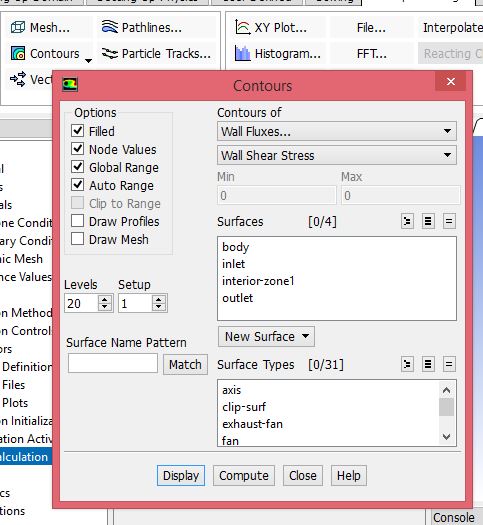
Yes, the differences in WSS regard the exact same case=aneurysm.Note! These were Max Values of WSS. Not Area Averaged.
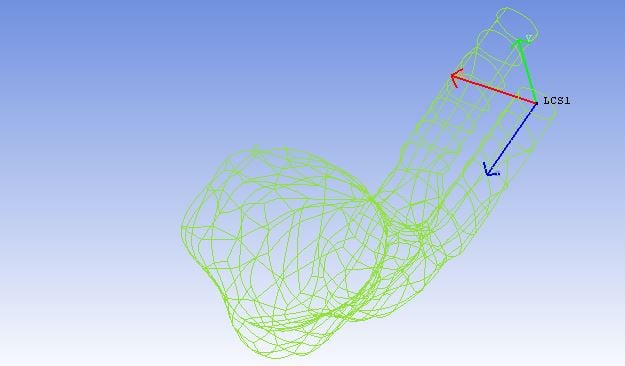
In the first try, I just leave the coordinates as they are. No translations or rotations are applied.
- Then I apply a constant magnitude of 0.8m/s at the velocity inlet from the boundary conditions section.
- Reference Values-Compute from inlet
Finally, 100 iterations are applied.
Max WSS; 206 Pa
Wall averaged WSS; 2.23 Pa
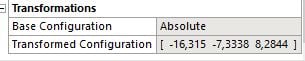
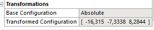
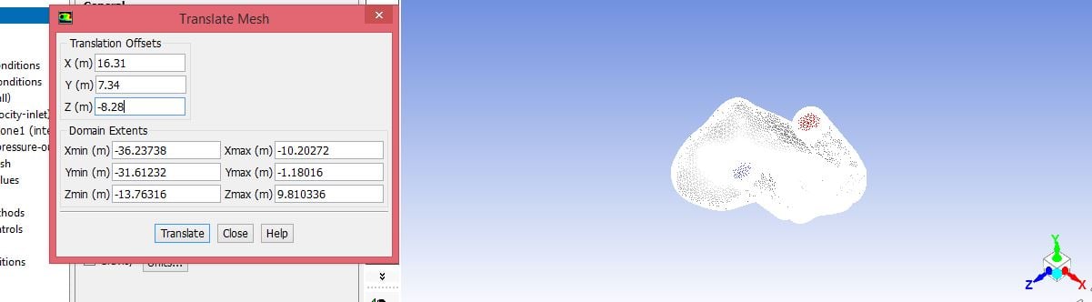
The second try has the Translate Mesh option applied. Remember the diameter of my mesh is 20mm. Translation as follows;
X=0.016m Y=0.007m Z=-0.0082m
The solution initialization is applied again i.e 0-100 iterations and the compute from Inlet option leads to different values.
Max WSS; 204Pa ie 1% difference without translation
Area Averaged WSS; 2.23 Pa
What happens if you run the case and then apply any translation meanwhile reporting max and area average of wall shear
It seems to change much,! If I run 0-100 iterations with the global coordinates and then translate the Y direction -10m & the Z direction +20m of the mesh ( whose diameter is 20mm and run 100-200 iterations), some drastic changes happen, at the Max Values.
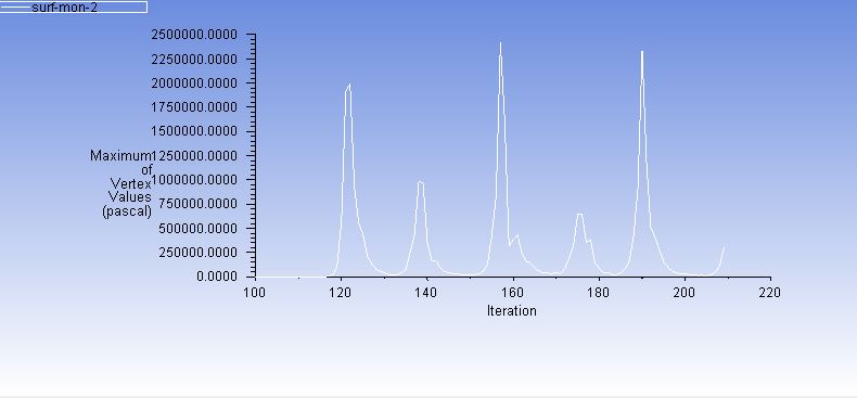
Max WSS; 297.678 Pa vs 206
Area Averaged WSS; 2.88 Pa vs 2.23 i,e 22% difference
All of these happen if I apply those Huge (compared to my mesh size), translations.
If I apply transaltions in the order of mm I can merely see any differences.
.
-
December 12, 2018 at 3:24 pm
superduke1200
Subscriberto rwoolhou
The previous post,which was an answer to Abenhadj possibly covers your question.
Only the Max value changes, if I apply those great transaltions of meters. The area averaged does not seem to change much even in this extreme case 2.23 vs 2.88!
Does this mean that I do not need to have the origin of my coordinate system aligned, for whatever I need to calculate?
For example, above WSS there is another critical parameter which defines whether an aneurysm will rupture or NOT.
It is called OSI (Oscilattory Shear Index) and the way to calculate it is the following custom function, imported in Fluent;
0.5 * (1 - (sqrt (mean-x-wall-shear ^ 2 + mean-y-wall-shear ^ 2 + mean-z-wall-shear ^ 2) / mean-wall-shear))
The mean values are time averaged ones and as someone can see it has x, y, z components. Won't it matter if I apply different angles and locations on my coordinate system?
-
December 12, 2018 at 3:56 pm
Amine Ben Hadj Ali
Ansys EmployeeDoes the run stop because of the issued number of iterations or by residual convergence or by report convergence. Please let your case run for more iterations till the max-value does not change anymore.
Can you moreover post screenshot of wall shear contour at the wall for both cases where the location of maximum might be seen?
-
December 15, 2018 at 10:22 am
superduke1200
SubscriberDear Amine,
apologies for the delayed response.
I had to make some revisions at the previous posts, because of a mistake in the dimensions of my mesh.
Now everything has been updated with the correct values.
It finally seems that when a Mesh of mm's, undergoes a translation of mm's nothing drastic happens.
Subsequently, I think that the origin of my coordinate system does not matter in my case.
-
December 15, 2018 at 2:23 pm
Amine Ben Hadj Ali
Ansys EmployeeGreat that by sticking to the right dimensions everything is good. Please mark this thread as solved.
-
December 15, 2018 at 4:08 pm
superduke1200
SubscriberFinally, there is something that I would like to share with future readers;
by translating the mesh in Fluent, I expected that the X,Y,Z components of Wall Shear Stress or Velocity contours for example, would certainly change.
To my surprise, that is not the case. I have graphs of area averaged and Max values of these components, but NO change is observed!
It would be interesting to find out why, translating a mesh in respect to the coordinate system changes nothing in any direction. Maybe it is the method used by Fluent to evaluate the components that does not take under consideration the translation.
I am going to rotate my mesh as well and come back with the results.
-
January 9, 2019 at 7:23 pm
superduke1200
SubscriberRotation has been applied. Nothing has changed and the coordinate system origin does not affect any outcome!
-
- The topic ‘Coordinate system Import to Fluent’ is closed to new replies.
-
2979
-
970
-
857
-
750
-
599
© 2025 Copyright ANSYS, Inc. All rights reserved.