-
-
September 7, 2020 at 12:04 am
SHADY_sh
SubscriberI am doing electromagnetic-structural coupling simulation. The electromagnetic part in Maxwell 3D is done without any problem. But for structural analysis in Ansys workbench getting convergence error. Can I have a suggestion to fix this error in Ansys 18.2?
Please find the attached outfile of solution information.
Thank you,
Mosarraf
-
September 7, 2020 at 2:50 pm
SHADY_sh
SubscriberI appreciate any help, please let me know if you need more informationn -
September 7, 2020 at 2:57 pm
peteroznewman
SubscriberPlease show the N-R Force Residual plot. How many substeps converged?nPlease show the Step Controls, what is the Initial, Minimum and Maximum Step sizes?nPlease show the material definitions.n -
September 7, 2020 at 3:26 pm
SHADY_sh
SubscriberThank you for replying. nCan I send you a copy of the program? n -
September 7, 2020 at 3:47 pm
SHADY_sh
Subscriber -
September 7, 2020 at 7:34 pm
peteroznewman
SubscriberIs the substrate an elastomer? Some kind of rubber? Those materials are nearly incompressible and have low values of Young's Modulus. ANSYS provides a large number of material models suitable for modeling elastomers. These material models are much better at converging than the linear elastic material models you are using. In addition, several optional parameters can be used that greatly assist in bringing the solution to convergence, such as Mixed u-P element formulation keyopt(6)=1 as well as other settings.nIt might also be that you don't have a fine enough mesh on the coating. How many elements are on the coating. Please show an image of the mesh.nFinally, you can attach a zip file to your reply with the paperclip icon. In Workbench, do File, Archive to save a .wbpz file. Then put that file into a .zip file.n -
September 7, 2020 at 8:57 pm
SHADY_sh
SubscriberThank you for your reply.nYes, the substrate is PDMS. I haven't used hyperelastic models before (if that what you were pointing to), also I prefer to use the linear elastic models because the results are compared to a theory which based on linear elasticity. nRegarding to the mesh, The thickness of the top layer is 0.1 um, the elements along this layer have same size as shown in the image. I also used element size of 0.05 um, two layers of elements along the thickness, however, the results are same.nnPlease find the uploaded file.nThank you.nn
-
September 8, 2020 at 4:42 am
peteroznewman
SubscriberI changed this to a two-step solution, because you are both squeezing the rubber and pushing a point load down at the center of the coating.nAs the model title states, this is an instability problem. If you squeeze then push, the surface is going to suddenly buckle. It is very difficult for the solver to jump into the buckled state. Some of the numerical methods that help it to do that are not available in 2D Plane Strain.nThe push then squeeze order pre-buckles the surface making it easier for the solver to make more progress.nn -
September 8, 2020 at 11:34 am
Erik Kostson
Ansys EmployeeHinnFor nonlinear instability, the stabilization under analysis settings and nonlinear controls helps - I would say to start low and take it up to say 0.15 with the reduced option.nnAlso there is an option to use the quasi static option under analysis settings, that would help as well with the buckling like Peter mentioned - is that also what you see in experiments, because that is hard to capture, and I doubt any linear analytical solution would capture that ?.Try that and see how it goes - obviously like Peter said, it is important to use correct material description for the coating.nnAll the bestn -
September 8, 2020 at 4:12 pm
SHADY_sh
SubscriberThank you all for your help.nnThe purpose of the point load here is to initiate an imperfection (perturbation) on the surface to help the surface to buckle when squeezing. nI have tried to solve your file, squeeze then push didn't solve (as you mentioned). The push then squeeze just solved 0.1 sec of the second step.nI am wondering, Did you get a solution for any of these cases?.Best Regards -
September 8, 2020 at 6:01 pm
peteroznewman
Subscriber
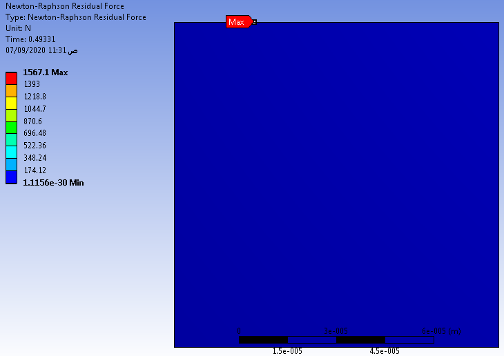
,nThank you for clarifying the purpose of the point load. In that case, I created a 4-step analysis: push, squeeze, stop pushing, squeeze some more. nStep 1: set the center point force to -1e-3 N in the Y direction.nStep 2: displace the left and right edges to +/- 0.2 microns to squeeze the rubbernStep 3: set the center point force to 0 NnStep 4: displace the left and right edges to +/- 2 microns to squeeze the rubber. nYou can see below that the solution stopped during step 4 at +/- 0.366 microns of displacement of the left and right edges. Is that enough for your purposes?nit was late when I posted the previous comment. I found Stabilization under Nonlinear Controls.n
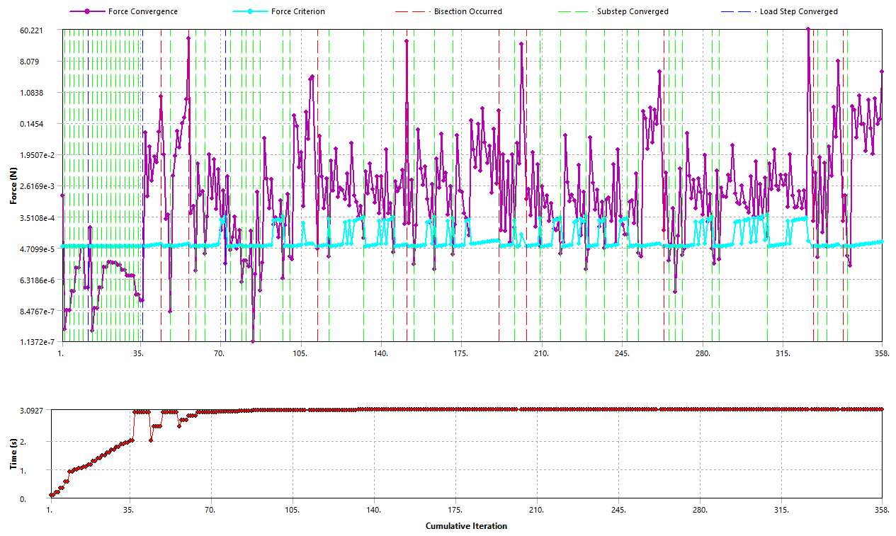
I don't often use this feature. Are these the settings you suggested. Below is the N-R Force Residual plot.n
Here is the error that stopped the solution:n
Here is that elementn
-
September 8, 2020 at 7:18 pm
peteroznewman
Subscriber -
September 8, 2020 at 7:20 pm
SHADY_sh
Subscriber@peteroznewmannThank you Peter so much for your help. I appreciate your effort.nUnfortunately the displacement you mentioned (+/- 0.366 microns) is not enough.nBefore, I was able to solve it to +/- 1 microns, and I hope I can reach +/- 5 microns.nCan you please attach the last file? That includes the results of your last comment.n@ekostsonnThank you for your suggestions.nThe stabilization option helped to push the analysis a little further.nThese are the values I used, Do you suggest any modification? nBest Regardsn
-
September 9, 2020 at 1:15 am
peteroznewman
SubscribernI posted the file I wrote about in the last long post in the very next post.nYour model solved it to +/- 1 micron, but you were using Bonded Contact and complained about the gap. There may have been some shear flexibility in the bonded contact. My model deleted all the Bonded Contact and used Shared Topology so had no gap and no extra shear flexibility.nYour model had 1 element through the coating thickness, my model had 2 elements through the coating thickness.nYour model was pushing and squeezing at the same time, my model had a more accurate buckled shape due to ramping off the perturbation force.nMy model runs within the Node and Element number limits of the Student license. It may be possible to get higher levels of compression if it was on the full license where I could get better shaped elements to solve by using more elements.nAre you on a full license or a student license?n
-
Viewing 13 reply threads
- The topic ‘Convergence Problem’ is closed to new replies.
Ansys Innovation Space
Trending discussions
Top Contributors
-
1997
-
897
-
599
-
591
-
444
Top Rated Tags
© 2025 Copyright ANSYS, Inc. All rights reserved.
Ansys does not support the usage of unauthorized Ansys software. Please visit www.ansys.com to obtain an official distribution.