TAGGED: convergence-error, plasticity
-
-
March 17, 2023 at 8:44 pm
Miguel Sanchez
SubscriberHi,
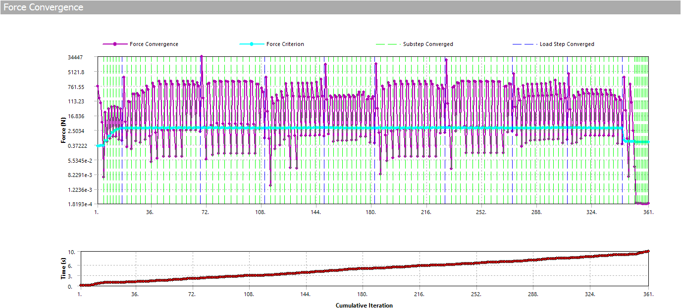
I managed to solve this multi-step static and fatigue analysis although it took quite a while (+7h):
wbpz file: https://drive.google.com/file/d/1GLN7kYbB-Y4gXPXdWAHAWJCXqSHh0Yjf/view?usp=share_link
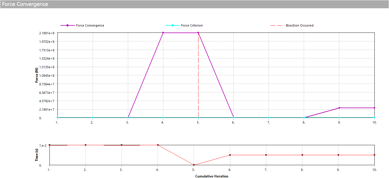
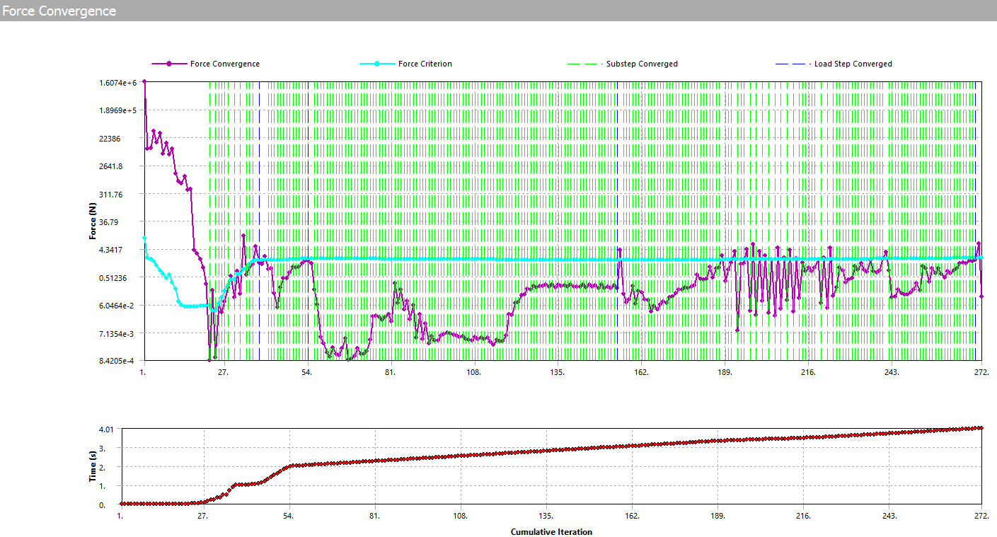
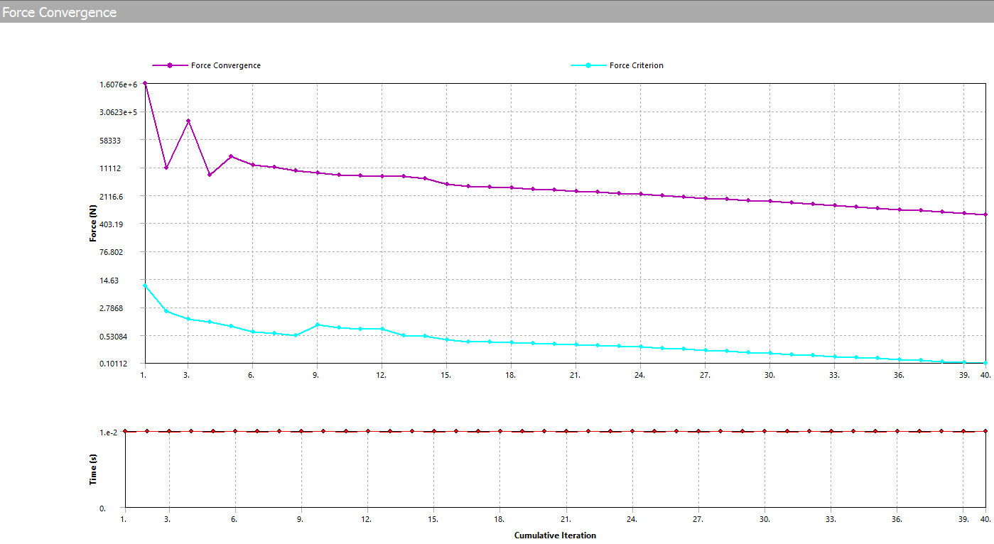
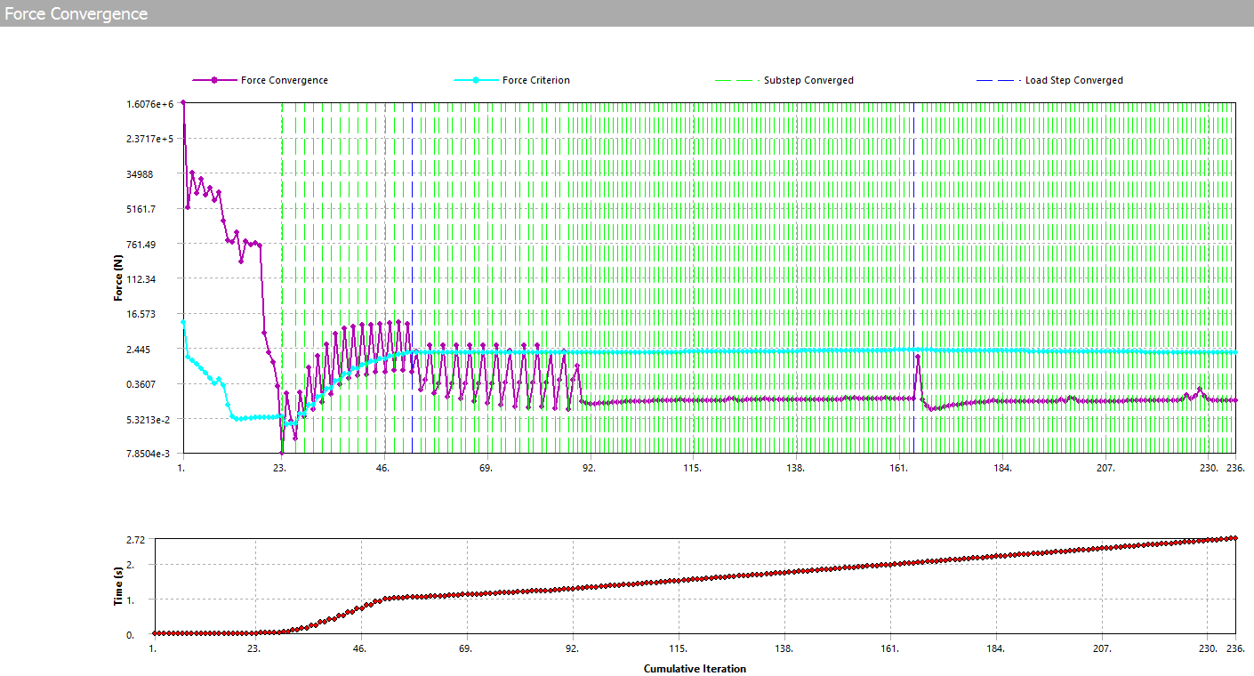
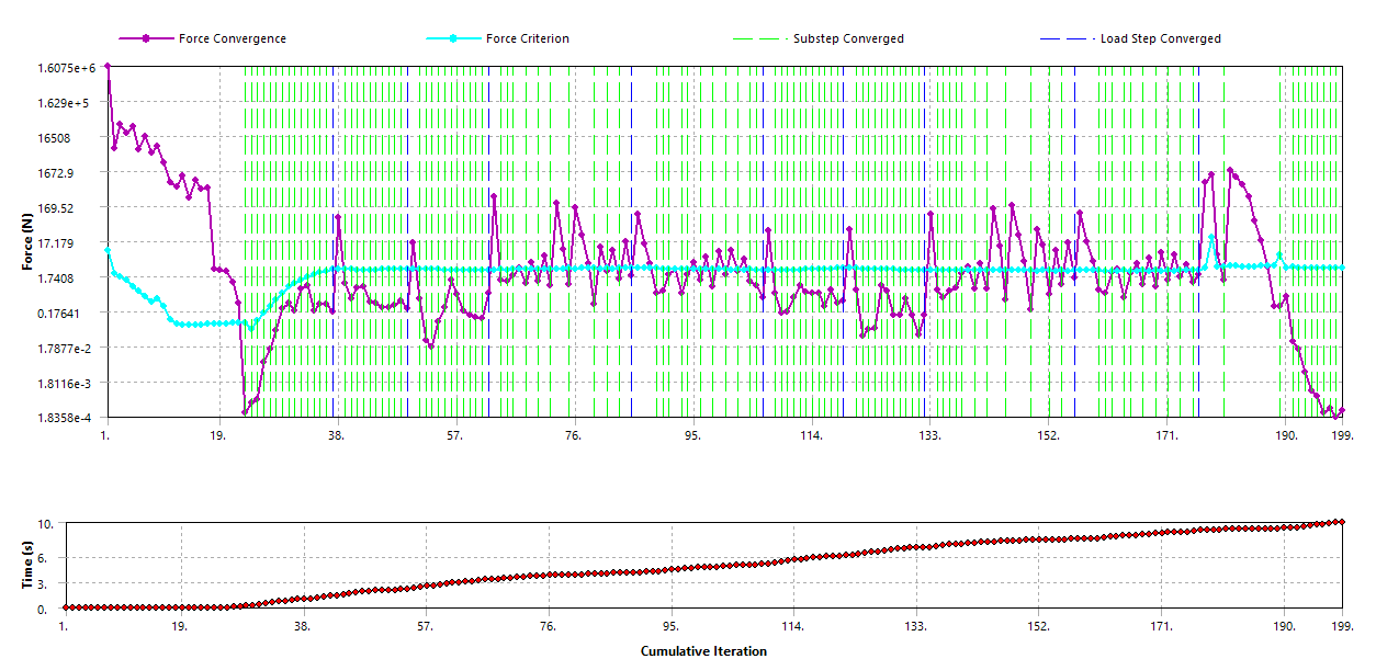
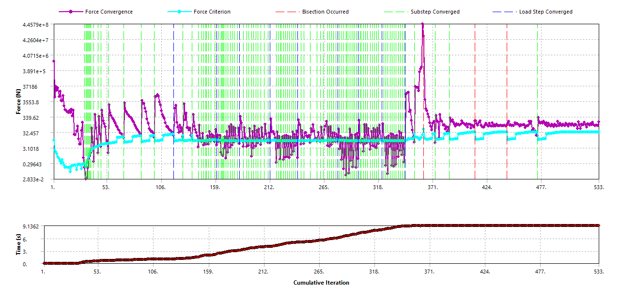
Now I just want to repeat exactly the same analysis but with a different plasticity model for the chosen materials (it was bilinear isotropic hardening before and I changed them now to kinematic hardening) keeping everything else the same. However the convergence troubles appear at the very beginning where before was a smooth and easy go...:
Any idea why or what am I missing?
Thanks
-
March 18, 2023 at 1:16 pm
peteroznewman
SubscriberYou didn't say what version of Ansys you are using, year and R#
-
March 18, 2023 at 4:43 pm
Miguel Sanchez
SubscriberYou re right Peter. I am using 2020R1. Why is this relevant?
-
-
March 18, 2023 at 11:40 pm
peteroznewman
SubscriberI have 5 versions of Ansys installed between 2 computers so I have only a 20% chance of starting the correct version and an 80% chance of starting the wrong version. If I start a version newer than 2020R1, then you won't be able to open the file after I save it. That wouldn't be ideal for you. Unfortunately, I don't have 2020R1, the oldest version I have is 2020R2 so you won't be able to open the file I save.
-
March 19, 2023 at 9:43 am
Miguel Sanchez
SubscriberRather relevant, I see. Is there something I could do to help with that setback?
Thanks anyway
-
-
March 19, 2023 at 2:06 pm
peteroznewman
SubscriberI opened your archive in 2020R2 to inspect your model.
First observation, if you kill the contact between the dead-weight and the board, you don’t need to lift the dead-weight up by 50 mm, you can leave it at 0, but that might still be a challenge since the board will have deformed in the -Z direction due to the 50 kg weight. It would be better to fix the pilot node at its current X,Y,Z displacement and X,Y,Z rotation in step 10, then kill the contact in step 11. But that is not the problem you are having, you are asking about gettting step 1 to solve.
Second observation, bonding the dead-weight to the board adds stiffness to the board. It would be more accurate to use Frictional Contact between the dead-weight and the board. That would allow the board to flex underneath the dead-weight.
Third observation, if you have a beam connection between the brackets and the board, a good simplification is to suppress or delete all the No Separation contacts between the board and the other corner components since the board is going to become concave from the dead-weight and will want to lift off those surfaces. I did that in case that helped the solution to advance.
While solving, there is a warning to pay attention to:
 Range of element maximum matrix coefficients in global coordinates
 Maximum = 3.06829627E+09 at element 87302.
 Minimum = 4.994212815E-05 at element 110614.

 *** WARNING ***                         CP =      64.047   TIME= 10:51:55
 Coefficient ratio exceeds 1.0e8 – Check results.
The ratio is approx. 6e+13 which implies an ill conditioned system and those do not give accurate results.
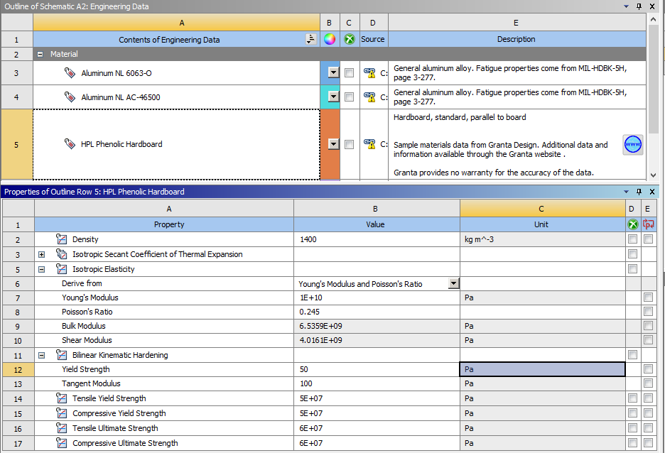
Looking at the materials, I see where you have made a mistake. You have entered the Yield Strength as 50 Pa instead of 50 MPa.When material property values are off by a factor of 1e6, that tends to cause problems.I changed the Bonded Contact between the dead-weight and the board to Frictional. Checking Initial Contact Status showed a problem.
To correct this problem, I changed the Interface Treatment to Adjust to Touch.
I changed the Initial Substeps on Load Step 1 to be 100, but it hasn’t converged with larger values for Yield Strength.
I changed the dead-weight from Rigid to Flexible, that got rid of the first error.
Now it starts solving. Getting the resut of the steps to solve might be accomplished by smaller initial step sizes.
-
March 19, 2023 at 7:16 pm
Miguel Sanchez
SubscriberThanks Peter,
- I see your point about not needing to lift the weight 50mm in the last 10th step. My idea was to show clearly (later in images for profane viewers) this has been retired and the table in its final exempt position. However I don´t quite understand your alternative of “fixing the pilot node…” and what the difference/advantage would be, or the problem with what I did…
- Fully agree but, how do I then keep the dead-weight from flying away in x/y directions and producing rigid-body motion problem? For example, if I set an additional remote-displacement for these DoF, I would be keeping it from moving when the table tends to drag it in those directions and would be also falsifying the real situation, wouldn´t I? May be a rough contact would do the trick?
- I am with you in this remark: in fact, I started with all-bonded contacts to make things easier and after that ran several configurations changing some bonded to no-separation and then to frictional trying to approach to the most reallistic model. I managed to solve them all but they all shared isotropic-hardening plasticity model for materials. Then when I changed the materials model to kinematic-hardening is when I began to encounter convergence problems and distorted elements appearing (which did not exist in formerly successful runs mentioned)…
- Here I enter in more swampy ground: I don´t know what this coefficient ratio refer to and how to deal with it. Regarding increasing results accuracy I tried to run a case using adaptive convergence but in this case I failed as I exposed in this other post: /forum/forums/topic/adaptive-convergence-for-accuracy/
Any other hint or suggestion you might have?
-
March 19, 2023 at 7:31 pm
Miguel Sanchez
SubscriberI see the mistake with the yield strenght (Pa for MPa) in the materials definition was not in my previous runs: Thanks for that!
Regarding the use of flexible/rigid behaviour for some parts when you don´t really need them / care about their deformation I usually have conflicts: I tend to define them as rigid to avoid meshing them but then I usually run into limitations/restrictions like the kind of contacts, joints you can use with them... Are there any best practices or hints in this respect?
-
March 20, 2023 at 8:38 am
-
-
March 20, 2023 at 11:59 am
peteroznewman
Subscriber1. Since lifting it 50 mm worked in the other simulation, it's fine.
There is a method for a boundary condition such as a Displacement to be Dead in step 1 while a force or load is applied, then for whatever unknown displacement was found at the end of step 1 to be held fixed so a different load can be applied elsewhere on the model in step 2.2. Friction (or Rough) keeps the dead-weight from sliding around in X and Y.
3. I changed my mind after I saw that the boad was sagging below the side beams, so I unsuppressed the No Separation contacts for those, then converted them to Frictional contacts. This is runnning now and is solving very nicely.
4. Read this to understand why a large Max Ratio causes the solution to lose accuracy.
When it comes to frictional contact, Ansys seems to do better with flexible-flexible contact than it does when one side becomes rigid. My approach is to start off with rigid because it saves some computational time, but if there are convergence issues, switch to flexible.
-
March 20, 2023 at 12:04 pm
peteroznewman
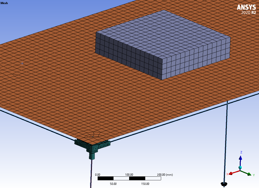
SubscriberI changed the mesh size on the board and dead-weight to a 20 mm element size.
If you can upgrade to 2020R2, I can send you my archive. Otherwise you will have to send me a new archive.
If you have a second computer, you can install the free Ansys Student license and open my archive. Don't install the free Student license on the same computer as your full Ansys license because those two installations are incompatible and you might mess up the full license.
-
March 20, 2023 at 12:45 pm
Miguel Sanchez
SubscriberUnfortunately my other computer is a Mac and is not prepared to run Windows either so... I´ll try to reproduce your las settings again and, should it fail again, will send you the new file.
Thanks for all again.
-
March 20, 2023 at 1:41 pm
Miguel Sanchez
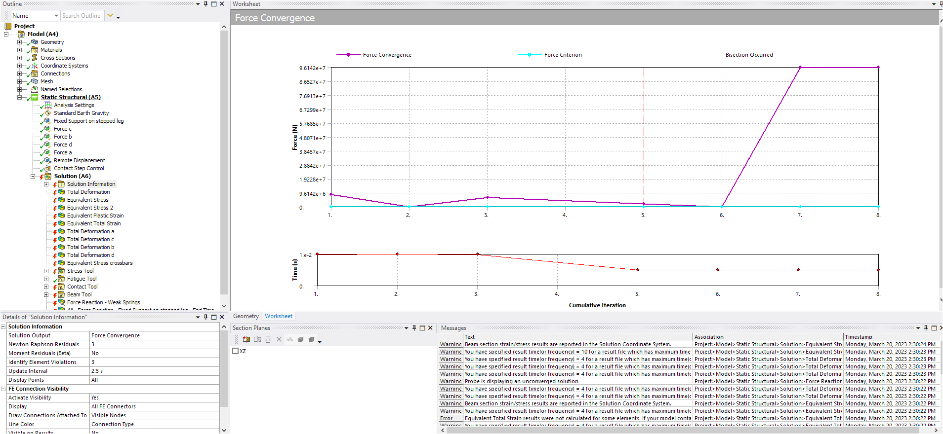
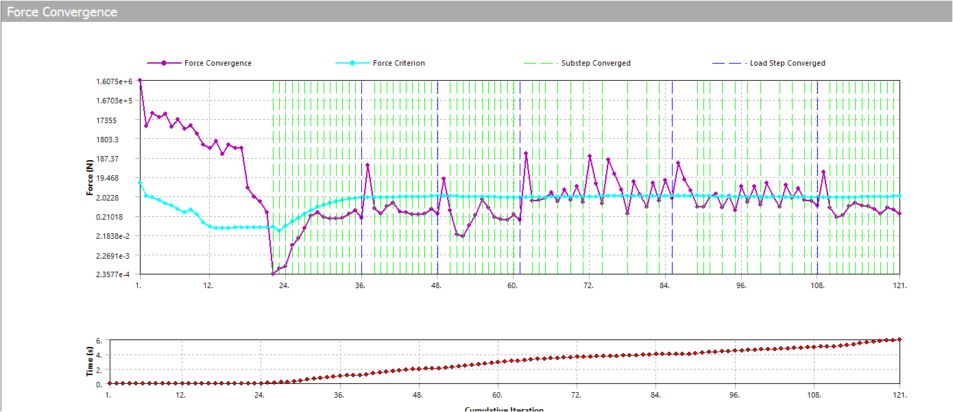
SubscriberI must be doing something wrong because I keep getting this:
Here, the new file: https://drive.google.com/file/d/1KX2w0mNyoieiOvitlv7z6AnjdJQ2rVZ9/view?usp=share_link
-
-
March 20, 2023 at 1:20 pm
peteroznewman
SubscriberI edited the properties of the Frictional Contact and changed the Normal Stiffness to a Factor of 0.1 which helps the contact to converge.
-
March 20, 2023 at 5:03 pm
peteroznewman
Subscriber- You forgot to fix the Yield Strength in the HPL phenolic board!!!
- The friction coefficient on the dead-weight to the table is 0. That is a problem. Use 0.1
- I changed the Normal Stiffness Factor to be 0.1 which may not be required.
- I changed the Minimum Substeps to 100 on every step from 10. Maybe a smaller number would work, look at the N-R Force convergence to decide.
- I added the command NEQIT,100 to tell the solver to iterate up to 100 times instead of the default 26 times on All steps.
ANSYS is automatically improving your model for you:
*** WARNING ***                         CP =       8.656   TIME= 13:04:43
 Section ID set 17 (and possibly others), with only 1 layer and 3 integration points, is associated with material plasticity.  The number of integration points will be changed to 5 for improved accuracy.
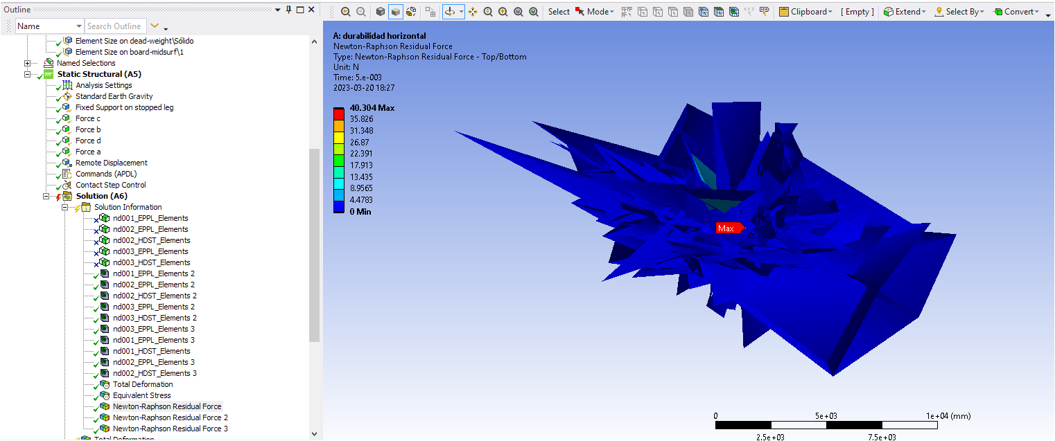
I will add a N-R Force residual plot after it runs for a few hours.
-
March 20, 2023 at 5:33 pm
Miguel Sanchez
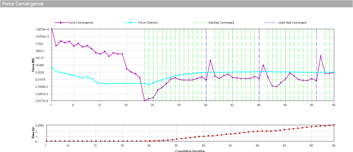
SubscriberI made all those changes... still the same. Lots of distorted elements and NR residuals don´t tell me anything I can understand/use...:
New file: https://drive.google.com/file/d/1N8UfIY3Pj0Fj1MFFApysN7mfuS_zxFaE/view?usp=sharing
-
March 20, 2023 at 6:54 pm
Miguel Sanchez
Subscriber- That must have happened inadvertently when I changed materials properties from isotropic to kinematic-hardening. Sorry about that. Already fixed... Now it seems to be on the right track:
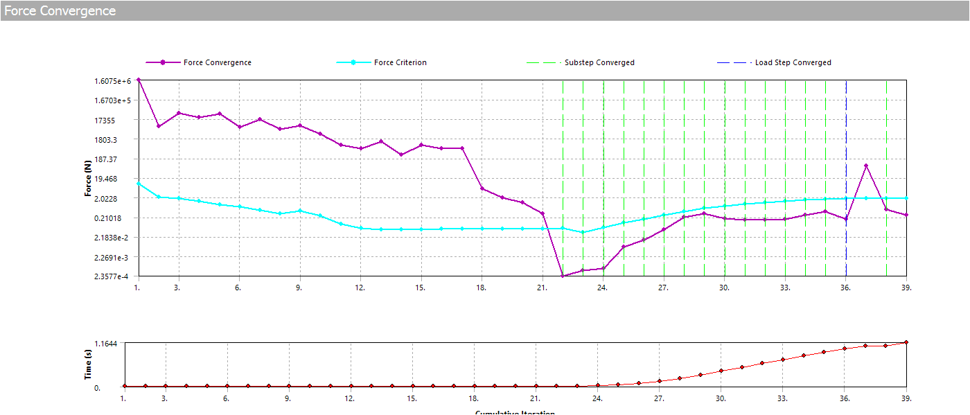
- I understand friction contact is enough to avoid the weight from flying away because inertial forces remain below friction forces, right?
* I read your link about "Adequacy of solutions" but find it hard to relate the math reasoning to a practical use of it to find what´s wrong in the model... isn´t there a more intuitive and direct way to find out what´s incorrect and what to do to improve/fix it? Or, at least, to understand how to establish that "maths <-> model" relationship?
* "Section ID set 17..." : How do you spot/identify this in the model? And why is that an improvement?
- That must have happened inadvertently when I changed materials properties from isotropic to kinematic-hardening. Sorry about that. Already fixed... Now it seems to be on the right track:
-
March 20, 2023 at 6:31 pm
peteroznewman
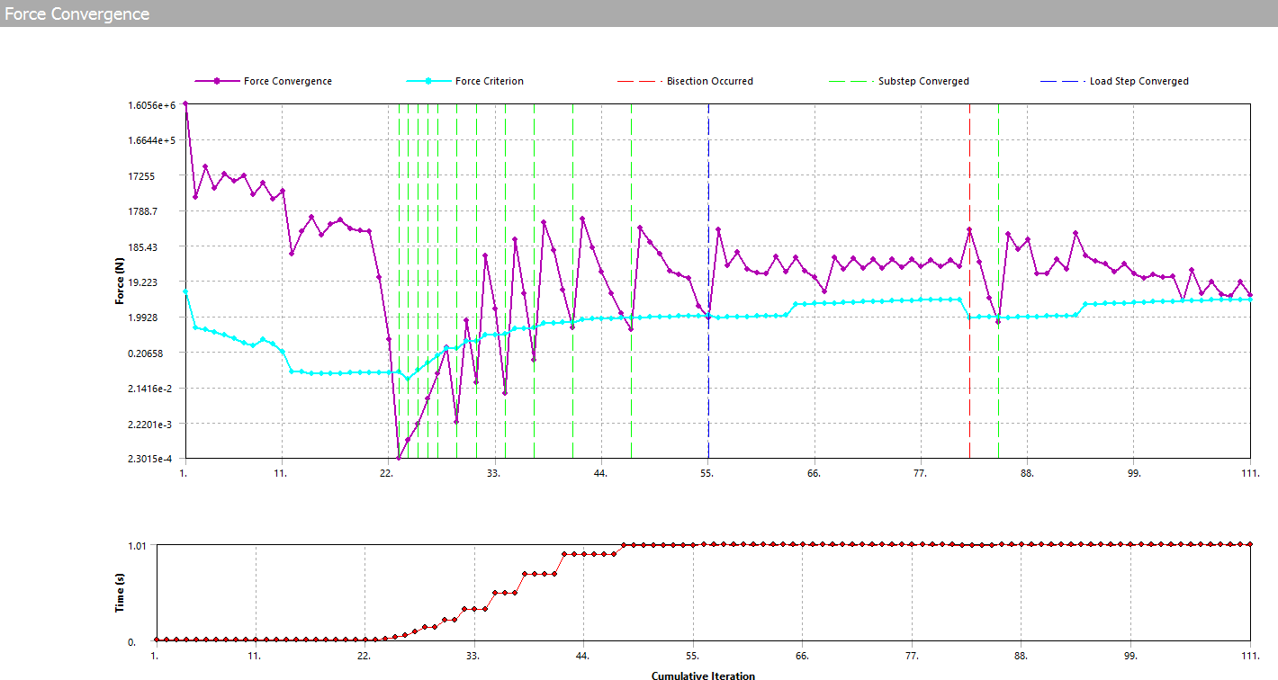
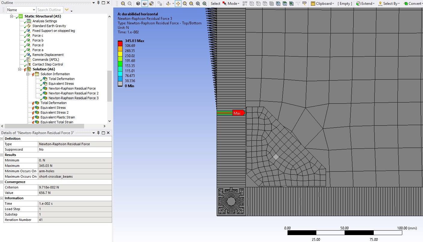
SubscriberIt’s not converging rapidly enough for my liking, so I pause the solve.
Then I look at the N-R Force Residual. The maximum is occuring on the short-crossbar_beams.
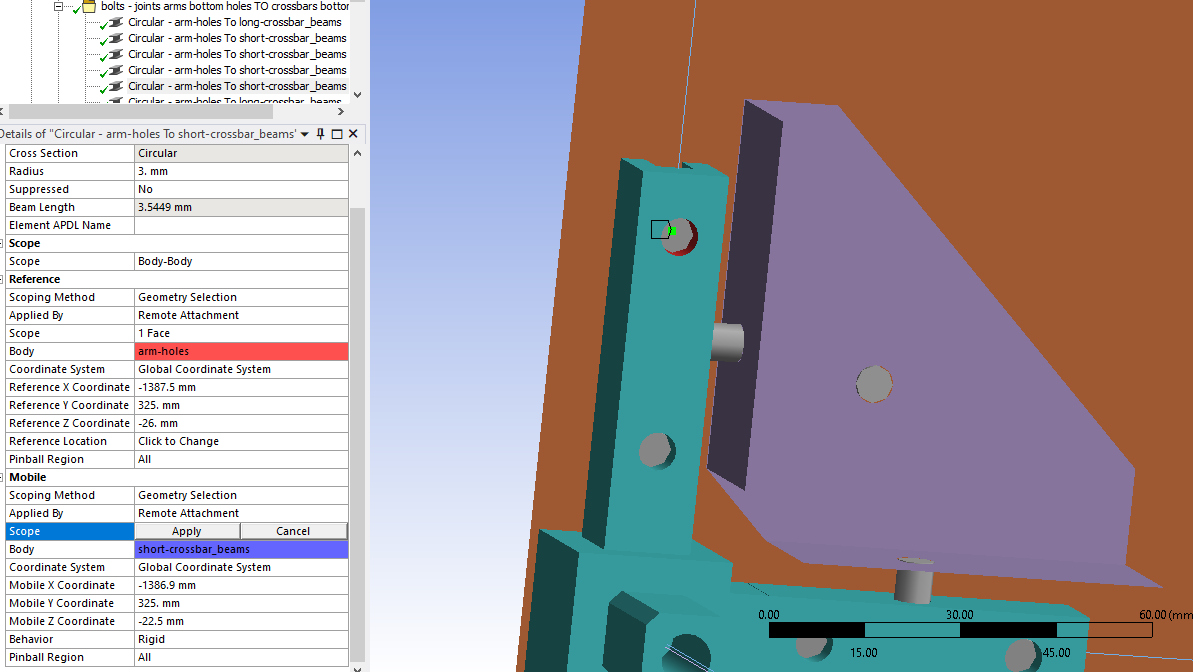
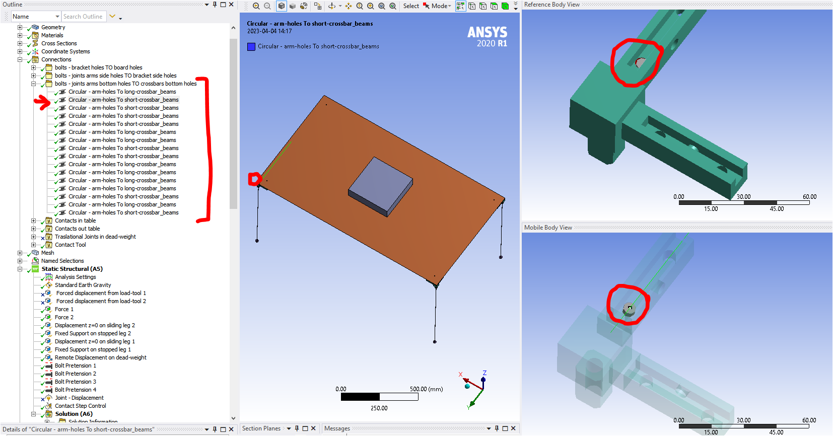
It looks like it is this bolt is having problems where it connects the vertex on the cross-beam to the corner solid hole.
So there is some useful information to figure out why convergence is going slow. It looks like that beam is trying to buckle out of a straight line.
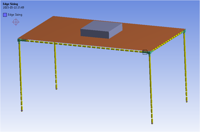
I remeshed all the line elements with an element size of 20 mm instead of 5 mm.
-
March 20, 2023 at 7:11 pm
Miguel Sanchez
SubscriberWhat´s this new graph from? The previous one looked much similar to mine and is quite fast:
¿?
Besides, the line elements in my model were mesh-refined with 2mm size. 5mm is the global sizing…¿? (when I meshed board and weight with 20mm size I got a warning message saying this was larger than global size and could be “inconvenient”… ¿?)
-
-
March 20, 2023 at 7:34 pm
peteroznewman
SubscriberYou get to set the global size and get to override that in mesh controls with generally smaller element sizes. It is alow allowed to override that mesh controls with a larger element size.
-
March 20, 2023 at 7:52 pm
peteroznewman
Subscriber-
March 20, 2023 at 8:06 pm
-
-
March 20, 2023 at 8:58 pm
peteroznewman
SubscriberPlasticity is known to require more substeps to converge than models with linear elastic materials.
You have to make a choice on how you want to spend your time. You can either use a small number of substeps, constantly monitoring the N-R plot and making adjustments to minimize the number of iterations, OR you can use a large number of iterations, walk away and do something else then return and be more likely to see the model converge to the end. If you use a small number of substeps and walk away, you are less likely to return and find the model has converged to the end.
If you are going to run the model many times to get some parametric curve, then it is valuable to tune the number of substeps to minimize the total number of iterations.
-
March 20, 2023 at 9:39 pm
Miguel Sanchez
SubscriberI get your point. Very instructive.
My model just converged so now I can compare both plasticity models, but after reading this other post from you (/forum/forums/topic/cyclic-elastic-plastic-simulation/) I start to think I might have to go another step deeper in complexity since with these analysis I intend to simulate one test with 20 cycles and another one with 20.000 cycles...
-
March 21, 2023 at 1:19 pm
Miguel Sanchez
SubscriberHi Peter,
About the remaining open issues (results accuracy with/without adaptive-convergence and beams results display), is there something more you can tell me to get them closed?
Thanks
-
-
March 21, 2023 at 2:39 pm
peteroznewman
SubscriberI don't use adaptive convergence. I prefer to manually refine elements near the high stress region. Adaptive convergence won't be useful in models that include a singularity because the stress increases without limit as the elements get smaller.
What is your question about beam results display?
-
March 21, 2023 at 3:30 pm
Miguel Sanchez
SubscriberFair enough. In other models adaptive-convergence worked fine for me and I find it convenient (when it works..) but I see your point about singularities so I might try to combine it with a submodel with rounded edges to get rid of them...
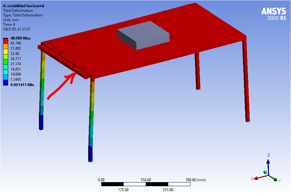
I explained my problem with the display of the short-crossbars beams results in this post: /forum/forums/topic/awkward-results-display/#post-252805 , which corresponds to the other test simulation with different loading conditions leading to larger deformations, but you can also watch it yourself (although less clearly) in the file I shared.
-
March 22, 2023 at 1:30 pm
Miguel Sanchez
SubscriberAny idea about that displaying issue?
-
-
March 22, 2023 at 4:30 pm
peteroznewman
SubscriberI believe the beam rendering will be greatly improved by using much longer beam elements. Instead of 2 mm element size on the beams, try 50 mm. Does that improve the beam rendering?
-
March 22, 2023 at 8:54 pm
-
March 23, 2023 at 7:06 pm
Miguel Sanchez
SubscriberAny other idea?
-
-
March 23, 2023 at 7:26 pm
peteroznewman
SubscriberIt looks like the beam has the wrong orientation or offset. Change one or both of those and put the beam back under the board.
-
March 23, 2023 at 9:27 pm
Miguel Sanchez
SubscriberPeter, I am sure I understand your suggestion: the crossbars line-bodies are extracted from the 3D original extruded beams with the design-intended positions (in this case, open longitudinal groove facing inward) so orientation and offset should, by default, be correct. Shouldn´t they?:
Or do you mean some other thing?
-
-
March 23, 2023 at 9:42 pm
peteroznewman
SubscriberYes, you should get exactly what you show in SpaceClaim in Mechanical, but if there is a bug in the code and the section was flipped or offset, then you would have to correct that manually. But perhaps the bug is in the code that renders the visualization on the results in Mechanical and the profile used by the solver on the beams in the finite element model are correct. You will have to do some work to figure out what the finite element model is actually using.
-
March 23, 2023 at 10:56 pm
Miguel Sanchez
SubscriberI would say the problem must be the your second guess since the beams orientation appear correct also in Mechanical:
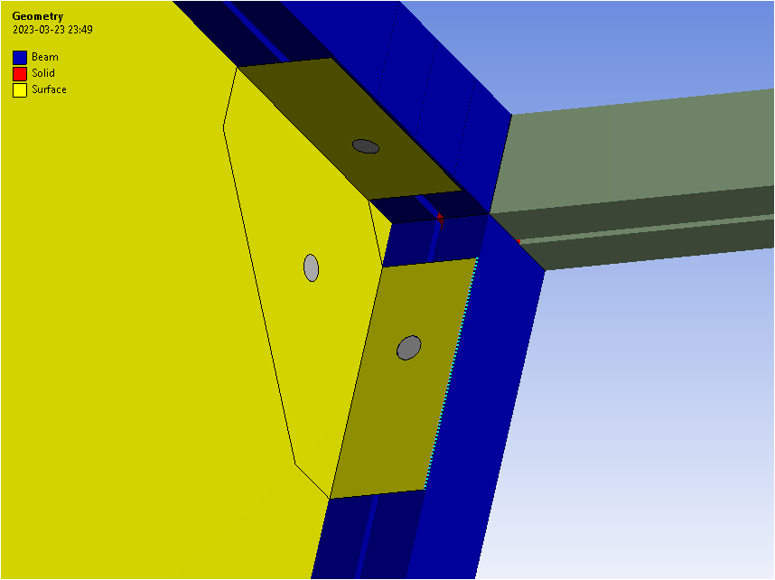
... but the original geometry rendering shows some defects too: the leg beams do not appear in their corresponding correct blue color...
So, what do I do with/after that? How the hell do you spot and correct a bug in the code?!
-
March 26, 2023 at 12:35 pm
Miguel Sanchez
SubscriberHi again Peter,
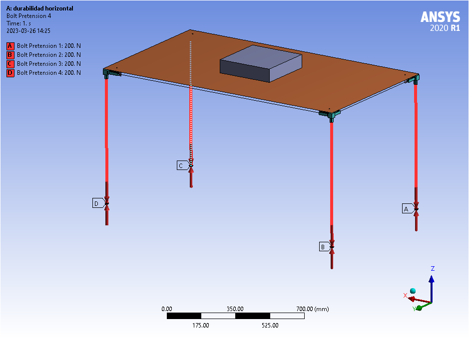
Coming back to convergence troubles...: so far I sidestepped the bolts pretensions. Once the model with different contact settings converged successfully I started adding these pretensions: it worked fine adding pretensions in the leg-rods first (to model the tightening through nuts in the leg tips):
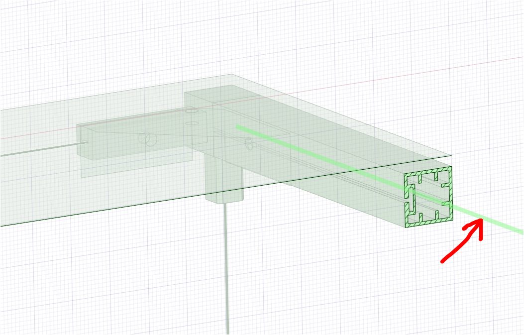
but when I also added pretensions in all the bolts (modeled as beams) in the corner joints, I stumbled again into trouble but, surprisingly, only in the final weight-lifting step:
Same thing happened with the other test but failing earlier in 6th step (out of 12). And I don´t find where the problem can be...
Would you be so kind to take a look at them to see what can be happening?
wbpz files (for both tests):
- https://drive.google.com/file/d/1y3hfnndmkuFEF7BPxw2YyrWbMams_B4E/view?usp=share_link
- https://drive.google.com/file/d/1DJQCprz8so57D2gLtxes4BE3IBo3CJEc/view?usp=share_link
Thanks once more.
-
April 4, 2023 at 12:20 pm
Miguel Sanchez
SubscriberHi Peter,
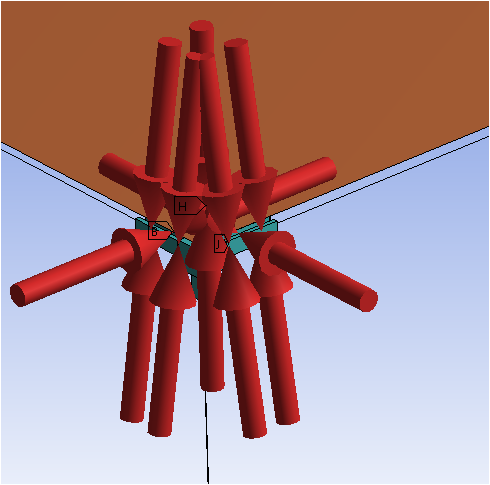
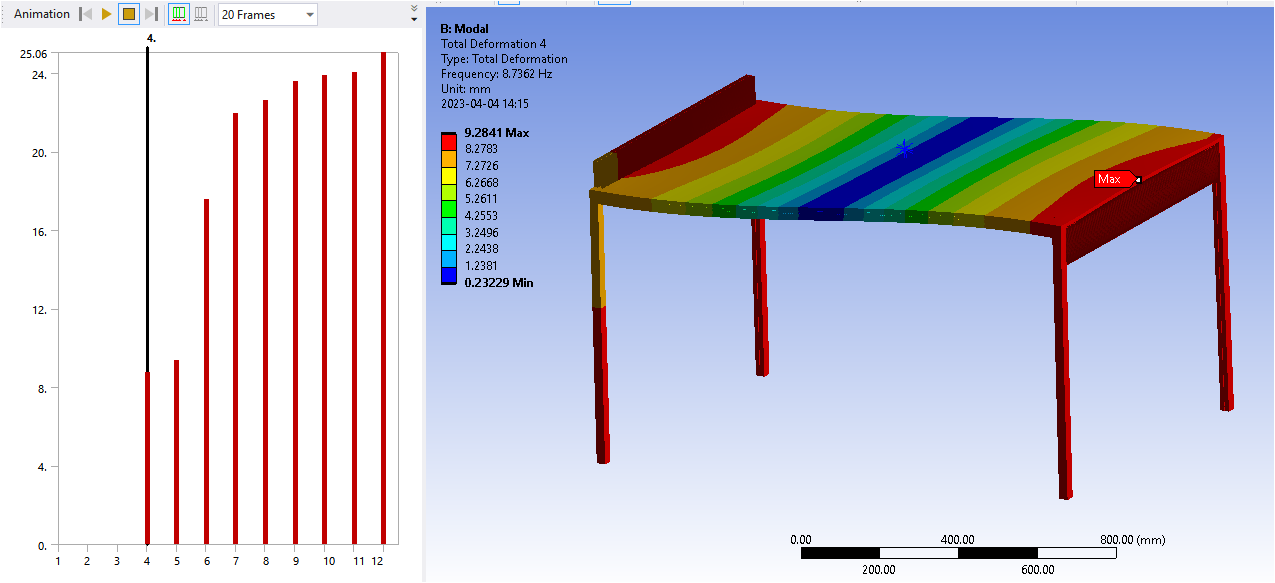
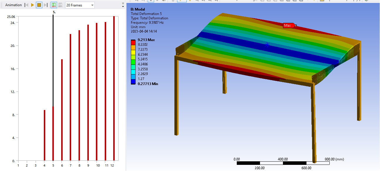
following the beams rendering issue, I thought I might be able to see whether and where the problem is by running a modal analysis of the structure. The outcome does not tell me much new: the same beams appear also somehow "wrong-connected" from the rest of the structure but they don´t fly away either:
I doubled checked their connections with the rest of the elements and they look ok, much the same as the other equivalent long-beams which don´t pose this problem...:
So I don´t know what else to do in order to figure this out...
-
-
March 26, 2023 at 12:50 pm
peteroznewman
SubscriberWhat is the purpose of the analysis? What questions do you want the model to answer? Do you need Bolt Pretension in the model to answer those questions?
I build models of structures with torqued down bolts but the global model has fixed joints or beam connections instead of bolts and has no contact because the area of interest is not near the bolted joint. There may also be a detailed model of the bolted joint interface, but it will be of a small section of the structure cutout to study using a more detailed mesh with solid elements instead of beams and shells. Can you apply this method of using a detailed model?
-
March 26, 2023 at 7:22 pm
-
March 27, 2023 at 9:56 am
Miguel Sanchez
SubscriberBesides, your explanation induces me a doubt: even if “the area of interest is not near the bolted joint” I ask myself: but wouldn´t the behaviour of this area be different in the prestressed structure when compared with the “un-stressed” one?
Isn´t it that the reason you can, e.g., import the results of a previous analysis as the initial pre-stressed state by linking two systems in the Project Schematic?
-
-
March 27, 2023 at 1:10 pm
peteroznewman
SubscriberSome structures, such as a guitar string or a drum skin, behave very different globally when there is a pretension than when there is not. Most bolted structures behave the same globally whether there is bolt pretension or not. It is only the local stresses in the parts around the bolt that change.
That is why you can often replace the expensive computation of bolt pretension and frictional contact with a simple beam connection or fixed joint to evaluate the global response. The detailed model is made by cutting out a small piece of the global model, one corner in your example. Ansys has methods to enable this type of modelling by transfering the displacements from the global model into the detailed model.
You still have to get the detailed model to converge, but the mesh can be different.
Thinking about your 20 cycles vs 20,000 cycles, you only need to do 1 cycle and look at the values of stress. If the stress is below yield, then the structure can survive the 20 cycles. To determine if there is a concern at 20,000 cycles, you need the SN fatigue data for the material and do a fatigue calculation to predict the life for the peak stress in that 1 cycle.
-
March 27, 2023 at 2:40 pm
Miguel Sanchez
SubscriberPretty much in agreement with you with the following caveats:
- stresses grow above yield already in the 1st cycle: although this can be considered itself to already invalidate the design alltogether I wanted to explore whether small plasticized, but not broken, areas could allow the table to remain stood up with negligible deformations after the whole test (we talked about this here: /forum/forums/topic/material-plasticity-models-and-breaking-point/#post-275310). Hence, the repeated cycle, the material model discussion and the intention to include also the pretensed bolted joints.
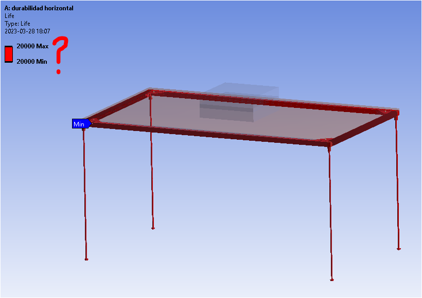
- I reckon 20.000 cycles are too few for SN-fatigue, therefore I intended to try with EN-low cycle analysis (as discussed here: /forum/forums/topic/low-cycle-fatigue/) but I am having some trouble interpreting the results:
Would you mind having a look at them?
The only remaining flaw is still about the weird rendering behaviour (/forum/forums/topic/awkward-results-display/#post-252805). Everyhting else, just like you said… so thanks a lot for that. It´s been very instructive and gratifying discussing with you.
-
March 29, 2023 at 11:11 am
Miguel Sanchez
SubscriberHi Peter, Did you see my last reply? Are you familiar with EN-low cycle fatigue analysis?
Thanks
-
-
March 29, 2023 at 2:01 pm
peter.newman
SubscriberHi Miguel,
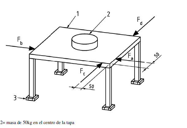
Yes I am familiar with EN low cycle fatigue analysis. I recommend reading Mechanical Behavior of Materials by Norman Dowling. Chapter 14 is the Strain-based approach to Fatigue. I generally do hand calculations for Fatigue and have not spent much time learning the functionality of the Ansys Fatigue Tool. Your model is complicated by the fact that one cycle is the sequential application of four loads: Fa, Fb, Fc, Fd. The peak strain in the model will be in a different location from load to load. Place a probe at the location of peak strain for each load, and record the stress and strain at that location for the other three loads. Each probe then shows 4 values of strain. Look at the probe with the largest peak value. The fatigue life on that part requires calculating the life for each load separately and then combining the life for each load using Miner’s rule.
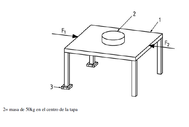
The same methodology applies to the other load case of F1 and F2. I see there is a different boundary condition on the feet. Two are secured and two feet are free to slide on the floor. This will cause higher stress to be on the corner above the secured feet. Does your model have different boundary conditions on the feet that are free to slide?
-
March 29, 2023 at 2:38 pm
Miguel Sanchez
SubscriberGreat Peter. I´ll try to replicate your directions and will keep you updated.
Thanks also for the recommended book. By the way, you say you don´t use the Mechanical Fatigue tool. For any particular reason? Do you know the Embedded-DesignLife nCode ACT? I've read it includes possibilities that are missing in the standard Fatigue tool...
Regarding your last question: the model with two secured feet and two sliding ones is for the 1st test simulation. In this case, the test just requires these last two legs to be free standing on the floor and asks for the table not to tip over when the forces are applied. I started trying a compression-only support for this BC using a 3D model of the feet (since it is unavailable for line-bodies vertex scoping) but I had some problems with that so I thought it´d be better to simplify it to a sliding support assuming that the reaction force result would tell me whether the legs get lifted or not… the outcome is they remain pressed against the floor during all the process so… far so good (I accepted). However, in this 1st case the test only requires 20 F1-F2 cycles to be performed so I reckon no fatigue is involved.
In any case, I learned I should have started explaining my purpose from the beginning rather than the particular pitfalls I was encounteering… Anyway, next time..
-
March 30, 2023 at 12:08 pm
Miguel Sanchez
SubscriberHi Peter,
Trying to follow your guidelines and learn more about Fatigue Analysis, I found this warning in ANSYS help about the capabilities in this area:
Since in my case I have a model with plasticity behaviour materials and stresses beyond the yield limit, I assume I cannot use this approach with ANSYS. Would you agree?
-
-
March 30, 2023 at 12:53 pm
peteroznewman
SubscriberI don't know for sure. It seems like Ansys has more work to do on the Fatigue Tool. Read the documentation for more information, but you might want to do your own hand calculations. I think if you use the nCode software, that has full capabilities, but it's not available in the free Student license.
-
March 30, 2023 at 5:04 pm
Miguel Sanchez
SubscriberThanks Peter. I´ll continue and keep you posted...
-
-
- The topic ‘Convergence issues with material model changes’ is closed to new replies.


-
4929
-
1623
-
1386
-
1242
-
1021

© 2026 Copyright ANSYS, Inc. All rights reserved.

