We’re updating our badges platform. Badge issuance is temporarily paused, but all completions are being recorded and will be fulfilled once the platform is live. Thank you for your patience.
General Mechanical

General Mechanical

Topics related to Mechanical Enterprise, Motion, Additive Print and more.

Convergence Issue for Parallel Platform (details hopefully show up this time)

    • Christian Berger
      Subscriber

      Hi,

      I’m running a static structural simulation with bendable metal rods (flexures) that I think requires me to have Large Deflection set to “On,” but I can’t get the solver to converge on a solution with that setting enabled. I’m wondering if there are additional constraints I could add or if there are other ways to simplify the model so that it can converge. I’m a beginner with Ansys, so I might be missing something glaringly obvious.

      The geometry is shown below. There are 6 flexures that connect the base platform to the top platform. The bottom face of the base is fixed. Both the base and the top are marked as flexible, but are thick enough that they don’t deform significantly. The connections between each flexure and the top/base are all bonded, except for the connections between the nearest four flexures and the base, which are frictionless. Four equal and separate forces are applied to the nearest four flexures to push them upward. The goal is to change the orientation of the top platform by pushing upwards on these four flexures. 

      An example of the Total Deformation when this force is applied is shown below. This example was run with Large Deflection set to “Off.” 

      Given the expected elasticity of the flexures, it seems very important that Large Deflection be set to “On” so that the solver does not assume they can be modeled with Hooke’s Law. However, anytime I try to run this simulation with Large Deflection On, I receive the following error: “The solver engine was unable to converge on a solution for the nonlinear problem as constrained.” 

      I have tried this simulation on several different computers, including computers specifically meant for running Ansys at my university. I have also tried simplifying the problem by reducing the amount of flexures that I apply force to. The solver converges with Large Deflection On when only two flexures are pushed (all others are bonded to the base). However, making just one more flexure/base connection frictionless (no force applied to it) renders the solver unable to converge.

      I have three questions:

      1. Am I right to assume that it’s vital that Large Deflection be set to “On” for this problem? 

      2. Are there methods to simplify this problem that I’m not using? Changing the element size of the mesh hasn’t seemed to impact the convergence issue. Nor has changing the amount of force applied to each flexure. The material of the flexures also hasn’t appeared to have an effect; I’ve tried Structural Steel, a custom Stainless Steel 316L that I defined by directly editing the properties of Structural Steel, and a custom hyperelastic Nitinol that is defined in the beginning of this video

      3. Should I resort to simplifying the geometry of this structure? This could be accomplished by reducing the amount of flexures, for example.

      Thanks in advance for any help with this

    • Ankush Choudhary
      Ansys Employee

      Hi Christian,

      Could you please try running  the model with Stabilization ON.

      https://ansyshelp.ansys.com/account/secured?returnurl=/Views/Secured/corp/v231/en/wb_sim/ds_stabil_energy.html?q=stabilization

      Thanks,

      Ankush

      • Christian Berger
        Subscriber

        Hi Ankush,

        Thanks for the advice! I’ve now tried using Stabilization with default parameters in both the constant/reduce and energy/damping methods, but I was still unable to converge. From what I can read, Stabilization helps when convergence can’t occur because of abrupt, unstable points like buckling. Nothing like buckling ever occurs for me. In fact, the solver does not finish solving more than 1 load step before it errors out. 

    • Christian Berger
      Subscriber

      q

    • peteroznewman
      Subscriber

      Hi Christian,

      If I understand the images, the flexures are solid bodies.  This model should be simplified.  Go into SpaceClaim and on the Prepare tab, in the Beams section click the Extract button then click on each of the solid flexures to convert them to beams. Then use the Midsurface button to extract a surface from the top disk.

      Open this geometry in Mechanical. Under the Connections folder, Insert a Joint to connect the ends of the beam to the holes in the top disk using Fixed Joints.

      You don’t need the bottom disk at all, suppress that. The bottom end of the beams can be connected to ground using either Fixed Joints or Translational Joints.  Add a Joint Load of type = Displacement to the four beams to move the bottom end of those beams up to cause the top disk to tilt. In the image below, I suppressed two legs to save time building the model.

      A different arrangement of six legs is called a Hexapod.  The six legs meet at 3 points on the disk. The six legs start at six separate points on the ground. Each leg has a spherical joint on each end.  As the leg length changes, the disk can be positioned in space at a wide range of angles.  No bending is required, this is a well-known mechanism design.

      • Christian Berger
        Subscriber

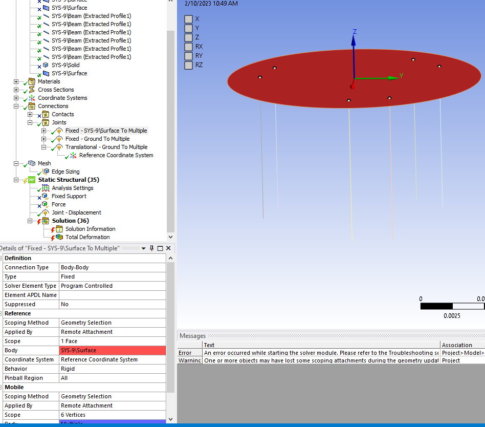
        Thanks so much for the info! I believe I've recreated what you have, but every time I try to solve, I get the following error: "An error occurred while starting the solver module. Please refer to the Troubleshooting section in the Ansys Mechanical User Guide for more information."

        No further info is given so I'll describe my setup in the hopes that what I've missed is very obvious.

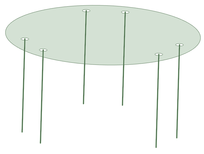
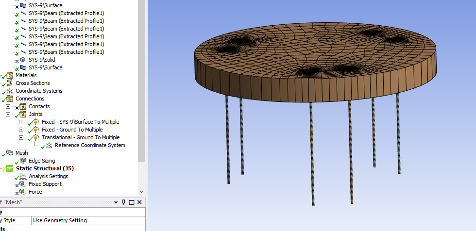
        The geometry is shown below. One surface and six beams are present; all other bodies are suppressed. The surface represents the top side of the top platform. The program asked for a thickness so I gave it a thickness of 2mm (extruded downwards). All bodies are Structural Steel for now.

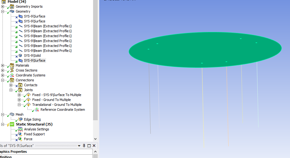
        The resulting mesh is shown below:

        A fixed joint is defined between the surface (Reference) and all the six top vertices of the flexures (mobile):

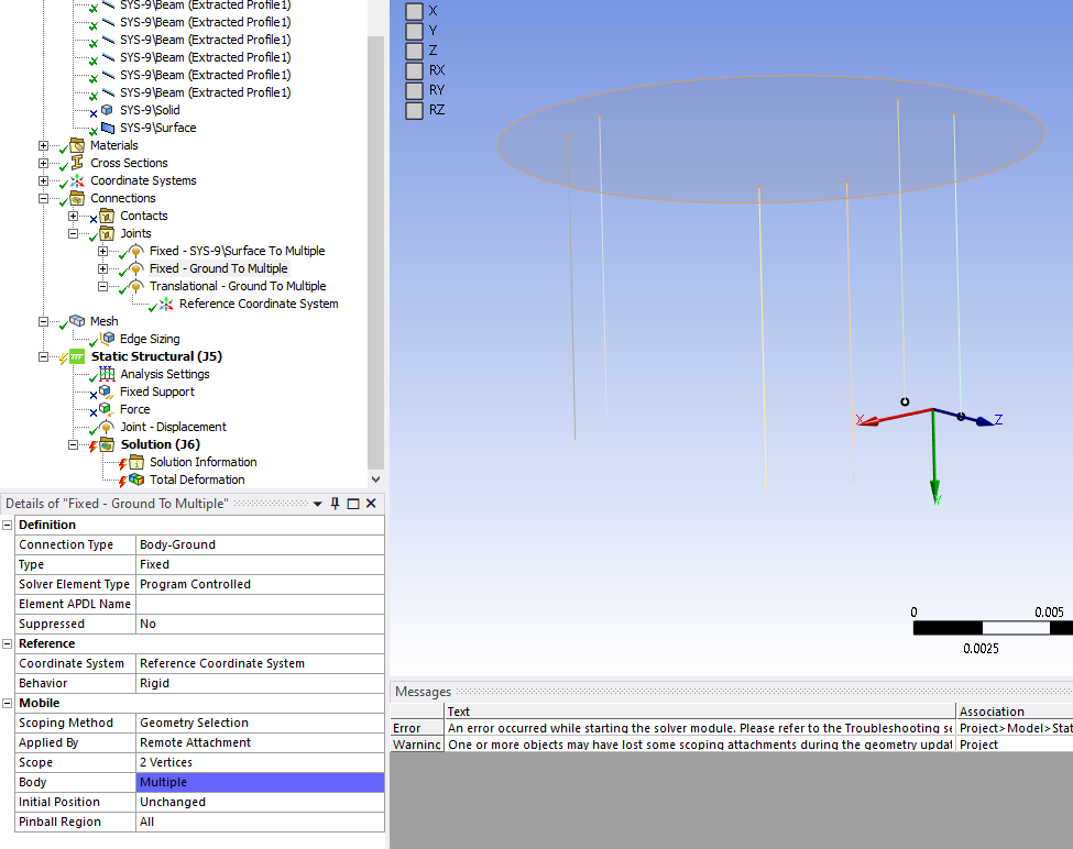
        Another fixed joint holds the bottom two vertices of the unmoved flexures to ground:

        A translational joint constrains the bottom vertices of the moveable four flexures to move in the upward direction:

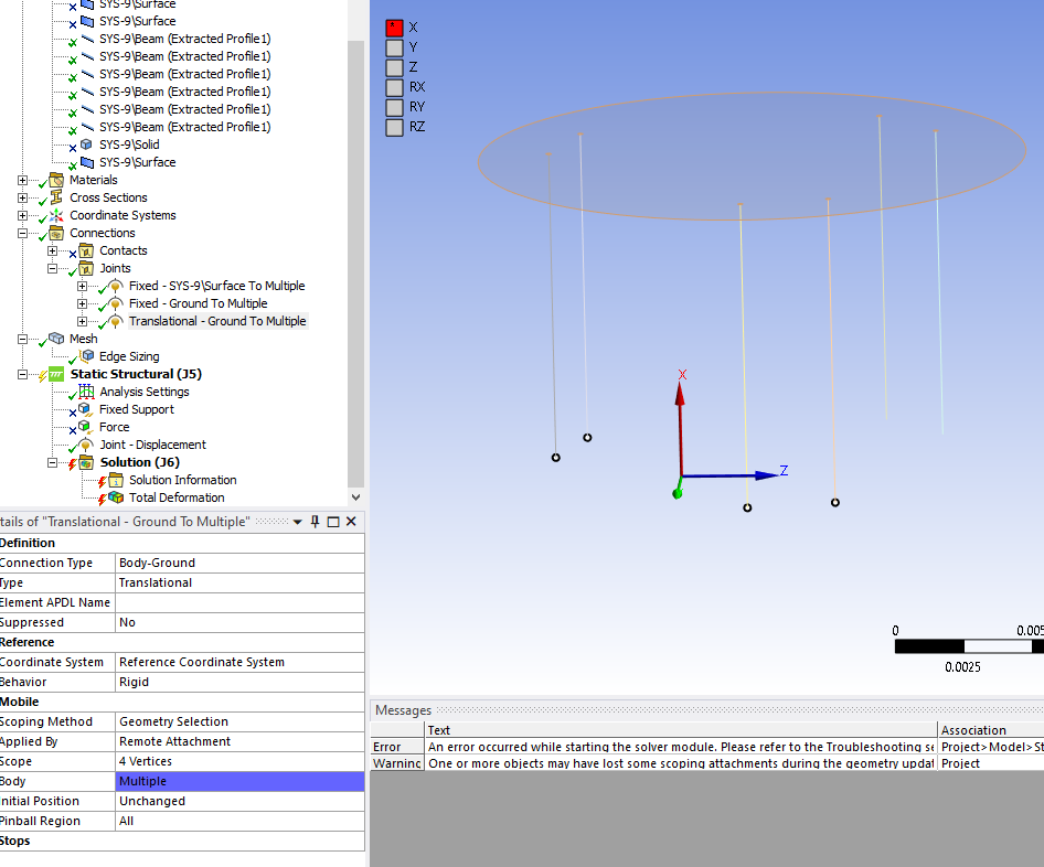
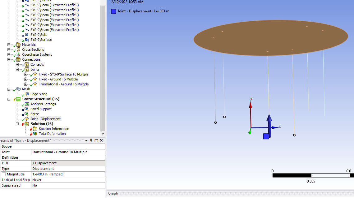
        A 1mm upward joint displacement is applied to this translational joint:

        Have I missed something important in my setup? I'm particularly concerned about how I define the top surface - yours appears 2D, but the program won't allow me to set mine to 2D.

        Thanks again for the help!

    • peteroznewman
      Subscriber

      To fix your model, try the following.

      Delete the Fixed Joint to ground.

      Use Fixed Supports on the four vertices that are on ground.

      Edit the Fixed Joint to surface and replace the surface with the six edges of the holes. Try to solve that. If it doesn't work, delete that joint and create a Fixed Joint between the edge of one hole and the beam vertex in that hole. Repeat for the other five holes/vertices to get six fixed joints on the disk.

      • Christian Berger
        Subscriber

        Thanks for the additional info! I tried all those options, but ended up with the same result. Continuing on the theme of enumerating each separate joint, I split every joint so that each referred to just one vertex and edge/ground pair. I also saw that I had recieved the following error earlier: "One or more objects may have lost some scoping attachments during the geometry update. You can identify these tree objects by filtering the tree using the Scoping option set to Partial." To make sure this wasn't the issue, I imported the same SpaceClaim file into a new static structural analysis and recreated the same model. I no longer received that error, but I get the same error stating that "An error occurred while starting the solver module." There are no other errors.

        Is there something else I can try? With how vague the error message is, I'm at a loss for next steps. I should mention, I'm currently using a student license, but I can try it on a full license if needed. I'm thinking my next steps will be to play with mesh element sizes (reduce them) and try to run the same simulation on Ansys-dedicated hardware (and a full license) at my university. 

    • peteroznewman
      Subscriber

      I built my model using Ansys Student 2022 R2.  If you have that version or a newer version, you can download the .wbpz archive from the link below and in Workbench, File Open and point to this file. It will solve on your computer.  Try changing the Joint Displacement to 5 mm for those two loads.

      https://jmp.sh/eSmXz3BR

      • Christian Berger
        Subscriber

        This solved it for me - I wasn't able to run your model on my laptop so I tried it out on the school computers and my version suddenly worked. Can't say thanks enough for the help!

Viewing 5 reply threads
  • The topic ‘Convergence Issue for Parallel Platform (details hopefully show up this time)’ is closed to new replies.