-
-
July 29, 2025 at 9:08 pm
scabo
SubscriberHi I am simulating solid-water in a pipe using E-E. I have defined the solid as a fluid material (from Materials>Create) and then given the density as that of sand keeping the viscosity unchanged. After that i am using a COUPLED, Pseudo time step and a steady state solution to run the flow. But the continutiiy term is diverging right from the beginning. What could be the problem with this? Do i have to modify the under-relaxation or something like this? Any help is greatly appreciated..thanks
It is showing ' Having convergence issues: Temporarily relaxing' and later on 'Divergence detected in AMG solver : Pressure Coupled', Floating point error.
-
July 30, 2025 at 8:55 am
Rob
Forum ModeratorWhat are the initial conditions? Try with transient too, getting an Eulerian model started in steady can be difficult if the flow field is very unsteady.
-
July 30, 2025 at 9:20 am
scabo
SubscriberHi. BCs are: 1) inlet: vel of water=sand, volume fraction of sand given. Theres a supersonic/initial gauge pressure for mixture which i have kept at default value=0 and Turb intensity and viscosity ratio as it is as. 2) Outlet I have given pressure BC and backflow of sand=0. 3) Walls-no slip for water and 0.1 spec coeff for sand. I am using kE RNG as turb model and have a good O-grid mesh with inflation layers with first layer height as 15 um. I have initialised with hybrid inititialisation.
As for schemes i am usignCoupled with2nd order for Mom, pressure and 1st order for others.
As for unsteady, some papers have done similar pipe problems using steady state, so i was trying the same.
Are all the settings okay? Do i have to change anything? thanks
-
July 30, 2025 at 9:31 am
Rob
Forum ModeratorWhat's the volume fraction of sand? Is the pipe horizontal? How big are the sand particles? Note a 15micron mesh implies inflation which implies high aspect ratio - that's not good for models where the result changes ALONG the cell.
-
July 30, 2025 at 9:39 am
scabo
SubscriberHi, Volume fraction of sand=0.19-0.4. Yes the pipe is horizontal, 3D and circular of length 70D where D is 0.103 m. Dia of sand=.09 mm. Are u saying first layer height =15 um is too big? Actually i wanted to see how the y+ comes and then adjust y+ =30 after the first run. But it keeps failing in the first attempt, I tried reducing the under-rlaxation factors for pressure and volume fraction, but no use.
Should i try with a reduced first layer height like 5 um? Or should i initialise with something else? thanks for giving advice.
-
July 30, 2025 at 9:49 am
-
July 30, 2025 at 10:23 am
Rob
Forum ModeratorIn E-G the particles can be larger than the cells but the benefits of y+ = 1 become less critical as you consider the multiphase drag. A very fine mesh for inflation means the aspect ratio is high, which isn't good for multiphase: aim for 1-2.
Next problem is the particle loading. Given sand sinks what do you think will happen in your model? How quickly will the system fill with sand?
-
July 30, 2025 at 10:31 am
scabo
SubscriberAbout y+=1, I was aiming for y+=30 because I am using the kE RNG model. What do you mean by 1-2? There is sand and water coming from the inlet at conc=0.19 of sand. So, the sytem will fill with sand relatively quickly i think. I think i can try by removing inflation first?
-
July 30, 2025 at 10:38 am
scabo
SubscriberBtw for defining the granular phase in the E-E framework i have defined air as fluid material and then just changed the density in the material box for air and called it sand. I hope this is the right procedure?
-
July 30, 2025 at 12:00 pm
scabo
SubscriberI was just asking, in these Eulerian-Eulerian problems how low can you expect the continuity to fall?I am seeing around 1e0 and getting stable results now. But the continuity is not falling around 1e-2 or something like that.
-
July 30, 2025 at 1:46 pm
Rob
Forum ModeratorMaterials are fine. Aspect ratio - you need to get somewhere near a value of 1 to 2, with a near wall cell at 15 microns that's going to be a very big mesh.
OK, so with a steady flow you expect to fill the pipe. But.... have you looked into slugging and duning effects? With a fixed inlet flow the fluid has to enter the domain.
-
July 30, 2025 at 3:03 pm
scabo
SubscriberSo you are saying I need a bigger first layer height to make the AR=1 near wall? Also i am now getting stable residuals with converged velocity for steady state after removing inflation layers but the y+=400. So i need to reduce the y+ to around 30 by imposing a first layer height. Is that correct?
-
July 30, 2025 at 3:08 pm
Rob
Forum ModeratorI am saying you need an aspect ratio near 1-2 for the mesh. Once sand piles up near the wall how do you think that interacts with the y+ theory?
-
July 30, 2025 at 3:14 pm
scabo
SubscriberYea, i do not know what will happen to y+ when sand piles up. Then the piled up sand will act as a wall also. But i am not sure how to mesh those scenarios. I dont think the fluent manual has that?
-
July 30, 2025 at 3:51 pm
Rob
Forum ModeratorNo, that'll not be covered.
-
July 30, 2025 at 4:53 pm
scabo
SubscriberI was also asking lets say i change the particle volume fraction or density or diamter. Can i start a new solution from a previous converged solution for the same mesh and pipe? I think it may be valid for the volume fraction but may not be for the other 2?
-
July 31, 2025 at 8:21 am
Rob
Forum ModeratorYes, with Fluent there's not always a need to reinitialise as we can just change a boundary condition and iterate. It's an old trick to reduce overall compute run times, we'd initialise & run, save case & data, change inlet velocity, run, save case & data etc.... Note for a transient calculation that does mean that time isn't reset.
-
July 31, 2025 at 9:18 am
scabo
SubscriberHi, thanks. Now I have run the simulation and it is producing stable residuals and converged quantities like vel mag and solid volume fraction in a steady state. But when i am plotting the chord averaged solid volume fraction along a vertical line it is deviating from experiments. What can be the issue? My sytem is not fully mesh independent as i wanted to use a coarse mesh first-but apart from that is there any issue? I have taken first layer as 0.5 mm and 4 inflation layers and y+=40. And i am using drag and other laws from papers.., thanks
-
July 31, 2025 at 10:26 am
Rob
Forum ModeratorHow long was the experiment running for? Steady state is an equilibrium state and I'd always check you were modelling the same conditions. Also, if duning occurs you may want to look at Rocky.
-
July 31, 2025 at 10:35 am
scabo
SubscriberHi, the simulation ran for 1.5 hrs on 30 cores and then it converged. Other papers have done steady state on the same xperimetnal conditions using commercial and got better results without Rocky. May be some problem with my mesh? I am using a corase mesh (1M) on a 7 m long pipe. But i will do the mesh independence..
-
July 31, 2025 at 10:36 am
Rob
Forum ModeratorI can't comment on other models, but mesh studies are always a good place to start.
-
July 31, 2025 at 10:46 am
scabo
SubscriberOkay-let me dothe mesh indp first
-
August 1, 2025 at 11:25 am
scabo
SubscriberHow do you calculate the pressure drop over a pipe lenght from the simulation results for slurry flows? Do we area average the pressure of water over the cross-section at 2 different locations anf then simply subtract?
-
August 1, 2025 at 11:32 am
Rob
Forum ModeratorSame as for single phase. But... you also need to consider what the experimental set up does.
-
August 1, 2025 at 11:54 am
scabo
SubscriberTbh, i am not fully sure for the single phase also. I can see that there is a derivative dp/dx in the plot section in Fluent but then how to get it to print a value over a certain length of the pipe?
-
August 1, 2025 at 12:14 pm
Rob
Forum ModeratorHave a look at the post processing in the tutorials.
-
August 1, 2025 at 1:34 pm
scabo
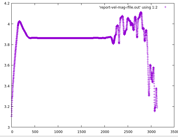
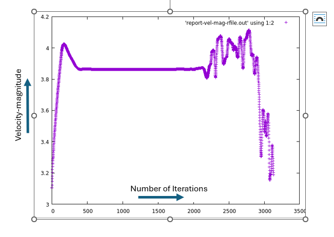
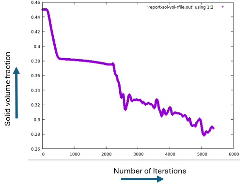
SubscriberI will have a look. If the vertex avg monitors for velocity, solid vol fraction, etc. becomes flat for some portion and then starts to oscillate at a point, does that mean we might need to reduce the under-rlaxation factors? or run it in unsteady state?
-
August 1, 2025 at 1:36 pm
-
August 1, 2025 at 1:53 pm
Rob
Forum ModeratorMaybe put titles on the plot?
-
August 1, 2025 at 2:04 pm
-
August 1, 2025 at 2:30 pm
Rob
Forum ModeratorWhat else is going on in the flow? One graph isn't enough to diagnose from. If you plot images every few iterations what's changing.
-
August 1, 2025 at 2:35 pm
scabo
SubscriberLike i am outputting the vel magnitude and solid volume concentration with iteration to check convergence of the solution. The solution converged for 14% sand concentration but is oscillating badly when i increase the sand conc to 45%. I think the solver is not able to handle the increased solid volume concentration? Do you want some of the results? like contour plots?
To you question whats changing-i think in this case everything is changing with iteration, it is not stabilising. -
August 1, 2025 at 3:06 pm
Rob
Forum ModeratorIf you have a higher volume fraction what might be happening in the pipe? The solver can handle the flow, but can you have a steady state solution, or is it transient?
-
August 1, 2025 at 3:10 pm
scabo
SubscriberIf i have a higher volume fraction, then the interaction between fluid and solid increases and also settling will increase, etc. I can run a transient case but other papers have got satisfactory results using a steady state approach which is what i am trying to double check.
-
August 1, 2025 at 3:13 pm
Rob
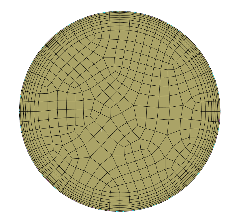
Forum ModeratorAnd if settling increases is there an equilibrium state? I can't comment on the paper, nor what settings were used as you've not shown me anything other than a (poor) mesh and a plot.
-
August 1, 2025 at 3:24 pm
scabo
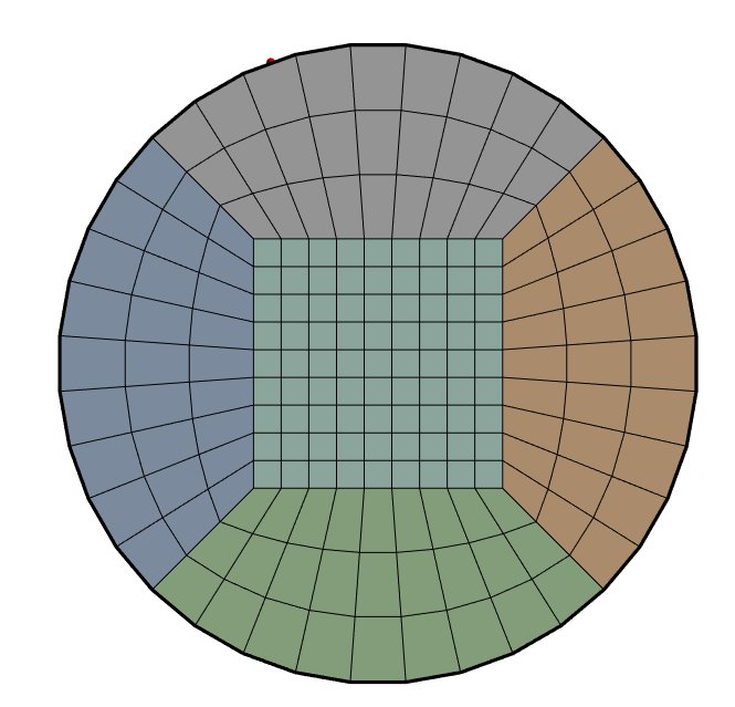
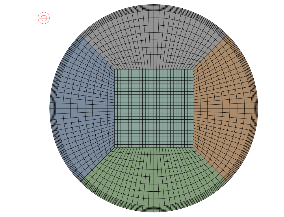
SubscriberI have improved the mesh from then and the solution converges for the 14% one. The aspect ration of mesh near wall is now around 2-3. The first layer height is 3e-4 m and 5 layers with a Growth rate of 1. The y+=50. Reducing the y+ to 30 gave poorer results when compared to exps. I have attached the mesh-Does it look fine?
-
August 1, 2025 at 3:29 pm
scabo
SubscriberAs for the papers they have steady state used phased simple algo with mom 2nd order and all 1st order. i have used the same. Does the multiphase parameters like drag law, specularity coeff, rest coeff affect the convergence?
-
August 1, 2025 at 3:34 pm
Rob
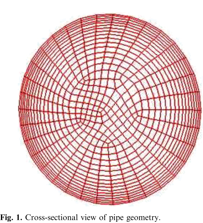
Forum ModeratorAnd the jump in cell size from inflation layer to core mesh? There's a reason we use pave meshes rather than O-grids. I've not built an O-grid in over 20 years as there's no need.
-
August 1, 2025 at 3:38 pm
-
August 1, 2025 at 3:44 pm
Rob
Forum ModeratorThat's a pave mesh. Inflation is a little excessive though.
-
August 1, 2025 at 3:49 pm
scabo
SubscriberOkay-i thought the mesh needs to be well oriented and symmetric and looking good. Thats why i went for the O grid mesh. I thought the above mesh is bad, but you are telling it might be better.
-
August 1, 2025 at 4:06 pm
Rob
Forum ModeratorBut is the flow well aligned with the O-grid when you have significant settling of the flow? The swept pave is also aligned with the flow too. There's a very good couple of slides in the training course but not so sure if it's in the AIS content covering the benefits of hex and tet for aligned and cross/off axis flows.
-
August 1, 2025 at 5:48 pm
scabo
SubscriberHi-thanks. Yes the flow can become asymetric when theres settling. I will have a look at the results and come back here.
-
August 1, 2025 at 8:51 pm
-
August 1, 2025 at 8:54 pm
-
August 2, 2025 at 12:12 pm
scabo
SubscriberHi The results are now converged and match with experiments. But i did not use any inflation layer in the mesh. The y+ is around 150 for k-epsilon RNG. Is it fine? Althought the results are matching wiht experimetns, my worry is because i did not use inflation layers is it capturing the Boundary layer properly?
-
August 3, 2025 at 8:35 pm
scabo
SubscriberHi. I have got a small issue. The solid volume fraction along the vertical symmetery line is perfectly matching with experiments, but the Eulerian model is overpredicting the pressure gradient by a big margin. This is contrary to literature as they report closer agreement using same model. have taken the difference of static pressure of the mixture at 2 different locations using area averaged method and divided by the distance of the 2 planes to calculate the pressure gradient.
Do I have to do something different?
-
August 4, 2025 at 10:20 am
Rob
Forum ModeratorUse a contour of pressure to better understand what's going on. As we don't know how the paper found dP it's possible they looked in the liquid part of the flow.
y+ is a mathematical construct to calculate "stuff" related to boundary layer flow and it's resolution. Once you add multiphase to the mix, how does the original concept and derivation stand up? You may need more near wall resolution, but also can't increase the aspect ratio too much: can you afford the cell count?
-
August 4, 2025 at 11:06 am
scabo
SubscriberCell count is not a problem as I have HPC at my uni. For multiphase flows, the AR is near 1-2 near wall as we previously discussed. I will look at the pressure contour but i found out one thing-if i reduce the specularity coefficient in the wall BC for grains-the pressure drop comes closer to the experiments. This may be because there is less mometum transfer from particles to the wall. Do you think this may be a fix?
Btw did u graduate from the CDT leeds fluid dynamics? i am from the same place. -
August 4, 2025 at 12:51 pm
Rob
Forum ModeratorLeeds?!? I went to a proper University! ;) Sheffield.
Possibly. It's not something I've tended to alter, but I also tend to be running more dispersed systems as I move to Rocky where significant sedimentation is likely.
-
August 4, 2025 at 12:56 pm
scabo
SubscriberOkay-thanks. There is one Rob who graduated from University of Leeds few years back who is also working in Ansys so i thought might be you-sorry for the confusion. But literature shows that without Rocky you can get good comparable results to experiments. My case is 45% grain concentration so still there is sedimentation but E-E without Rocky is able to capture it. May be i try the same case with Rocky and see the difference? I can send you one of the result comparing grain concentration profile along vertical line with exps usign E-E if you want?
-
August 4, 2025 at 1:12 pm
Rob
Forum ModeratorThere are two actually, I know both. One is still here.
The specularity coefficient may be a newer option, but it's not one I've played with. Depending on the level of sedimentation that may help mimic saltation effects. Rocky is a newer addition to the tool set, and helps where we need non-spherical particles or many sizes.
-
August 4, 2025 at 1:39 pm
scabo
SubscriberThanks for letting me know. I will get back here in case something required
-
August 4, 2025 at 1:43 pm
scabo
SubscriberAlso the Reynolds stress model with Eulerian doesnt give good results like kE RNG. I intend to pickup the secondary structures in an air-water flows with particles thats why trying the RSM model with E-E model. But the results are coming worse as compared to kE RNG.
-
August 4, 2025 at 2:08 pm
Rob
Forum ModeratorRSM tends to be more difficult to converge but you also need a to ALOT of studies before confirming something is better/worse: we use RSM for cyclone work with very good results. Note that the phase definition used in the Eulerian model mean you'll miss particle wakes so you may not see all of the secondary flow features.
-
August 4, 2025 at 3:35 pm
scabo
SubscriberYes okay. I was okay if it can capture the secondary flow features of the liquid. Just wanted to see the effect of secondary flow on particles with either and Eulerian-Eulerian or Eulerian DPM.
-
August 4, 2025 at 3:37 pm
scabo
SubscriberBut also it was written in one of the papers that to use kw model RSM BSL so that wall function could be avoided to properly capture the secondary structures near the wall. But in an E-E model in Fluent, RSM BSL is not present-theres only RSM Linear Pressure Strain which uses a wall fn, so might not capture the secondary flow near the wall accurately.
-
August 4, 2025 at 4:16 pm
Rob
Forum ModeratorPossibly, but, once you add a significant granular fraction how much turbulence are you expecting?
-
August 4, 2025 at 4:24 pm
scabo
SubscriberDo you mean how much I am expecting the secondary flow to affect the particles? If you mean this then there are some papers that have shown that secondary currents can affect the particle movement to some extent but they have mainly considered a lagrangian approach which might mean a dilute laden flow.
-
August 4, 2025 at 4:36 pm
Rob
Forum ModeratorVery probably.
-
August 4, 2025 at 4:52 pm
scabo
SubscriberBtw i cannot use a Eulerian_DPM for higher volume fractions like 15-30%? The software will likely fail right?
-
August 4, 2025 at 8:50 pm
scabo
SubscriberAnother thing i wanted to know if i want to do air, water, solid 3 phase pipe flow, like a partially filled pipe laden with particles-can I do the multi-fluid VOF or Can i use DPM in VOF model? Both will have some limitations i guess. Can you give some idea?
-
August 5, 2025 at 8:25 am
Rob
Forum ModeratorThe DPM model won't (usually) fail at higher loading but you'll not see the effect of particle volume in the domain and the settled mass has zero thickness.
You can use Eulerian without multifluid but check if you can have multifluid VOF and a granular phase - I can't remember. VOF and DPM will work but the DPM model won't see the free surface as anything other than a change in cell density & viscosity.
-
August 5, 2025 at 10:16 am
scabo
SubscriberThanks for letting these know.
-
August 5, 2025 at 12:29 pm
scabo
SubscriberAlso, in Eulerian model we cannot account for particle shape effect right? I am thinking what complexities can we add to the Eulerian model for particles apart from spherical particles?
-
August 5, 2025 at 12:45 pm
Rob
Forum ModeratorSpherical only, and diameter is only used for drag.
-
August 5, 2025 at 12:54 pm
scabo
Subscriberyeaa
-
August 6, 2025 at 11:16 am
scabo
SubscriberI was just asking in DEM you model individual particles right? so how much is the computation cost for say 45% grain concentration? Does it take days to run on say 40 cores for a 1M fluid mesh?
-
August 6, 2025 at 12:23 pm
Rob
Forum ModeratorRocky DEM uses a gpu (ideally) and compute load is based on particle count. They also have coarse graining which mimics the parcel concept in Fluent. It'll also take time to run, and time step is a function of collision speed (amongst other things): so it's a different time to run.
-
August 6, 2025 at 12:55 pm
scabo
SubscriberI understand-i have time in my PhD so thinking if could do Rocky
-
August 7, 2025 at 1:54 am
scabo
SubscriberHi-Also i was trying to model periodic slurry flows usign E-E model. It seems that it is a limitation? i cannot give the volume fraction of sand anywhere in the software and as a result it is showing zero volume fraction in the output. Is there anyway i can model periodic slurry flows using Eulerian-Eulerian model?
-
August 7, 2025 at 7:36 am
Rob
Forum ModeratorRead up on Patch. But also check whether a periodic section is suitable for the flow regime and model: periodic is repeating and infinitely long.
-
August 7, 2025 at 11:05 am
scabo
SubscriberI patched in the entire pipe volume, volume fraction of sand=.14 but what i saw that the monitor for solid volume fraction going to zero at a point in the domain. I think the sand is leaving the domain but not re-entering from the periodic inlet. For the BC i have just given the pressure gradient not anything else for both water and sand. Do i have to give some initial velocities for sand and water?
-
August 7, 2025 at 11:25 am
Rob
Forum ModeratorGood initial conditions tend to help. No sand at a point could just mean there’s no sand there, how is the volume report looking? You will also need to properly converge each time step.
-
August 7, 2025 at 11:31 am
scabo
SubscriberI will have a look and get back. Just to let know I am running steady state simulations for now because steady state gave good results matching with experiments for full pipes
-
August 12, 2025 at 9:57 am
scabo
SubscriberYou were telling that for multiphase drag AR of mesh near wall should be around 2. Is this for both Euler-Lagrange DPM and Euler-Euler? Because i wanted to use the RSM BSL turb model with particles, but it is unfortunately not available with the Euler Euler approach. But is available with DPM.
-
August 12, 2025 at 10:52 am
Rob
Forum ModeratorWork out which multiphase model is best suited to your application and then look at whatever other models are required. DPM is not designed for high volume fractions nor "blocking" effects making the concern about turbulence moot.
-
August 12, 2025 at 11:09 am
scabo
SubscriberNo i just wanted to study the secondary circulation and interaction with particles whether a dilute or dense flow. But RSM BSL is not available with E-E.
-
August 12, 2025 at 12:41 pm
Rob
Forum ModeratorRight, and how do you propose running a DENSE flow with DPM?
-
August 12, 2025 at 1:18 pm
scabo
SubscriberI was hoping the DPM solver would not fail (from our previous conversations) at higher concentration? say 15-45%. Or the results will be incorrect? In the guide it is written to use DPM when vol conc<10%. But i was hoping it will run for higher conce as well..
-
August 12, 2025 at 2:12 pm
Rob
Forum ModeratorRead what the DPM model is and does: there's a reason we don't recommend it's use over about 12-14% by volume. It will run at higher fractions, up to and exceeding about 250% volume fraction, but with somewhat dubious physical correctness.
-
August 12, 2025 at 2:40 pm
scabo
SubscriberOkay-let me read
-
August 13, 2025 at 10:56 am
scabo
SubscriberI was just asking-E-DPM tracks the individual particles and E-E does not. So, if i want to get the effect of particles on secondary currents-will both E-DPM and E-E give same and accurate results. This is becase the individual particle identity is lost in E-E method-thats why i was having this doubt.?
-
August 13, 2025 at 11:02 am
Rob
Forum ModeratorBoth results will be accurate but each model will behave based on it's underlying physics. You won't get the same results as DPM won't predict build up and E-E doesn't track a coherent parcel. Hence you needing to very carefully define your needs and understand what Fluent does. You may need to discuss with your supervisor.
-
August 13, 2025 at 11:03 am
scabo
SubscriberOkay-thanks very much
-
August 21, 2025 at 11:15 am
scabo
SubscriberHi. For an Eulerian-DPM solver if I have a periodic pipe then is it possible to include particles. The guide says that periodic particles are possible if they generate complete trajectories-does that mean deposition is not allowed in Periodic setups? thanks.,,
-
August 21, 2025 at 11:53 am
Rob
Forum ModeratorComplete means they are terminated somewhere, so either pass through or are trapped on hitting the wall. Neither of which are likely be fully representative of a long pipe.
-
August 21, 2025 at 1:00 pm
scabo
SubscriberAfter the flow reaches a steady state I can stop the simulation and introduce the lagrangian particles. The particles that are trapped are fine but what conditions are imposed on the particles that reaches the outlet? Are they re-introduced from the inlet?or destroyed in fluent periodic setups? I guess i need to see by simulating. Or do i have to do any UDF to introduce periodic particles in Fluent?
-
August 21, 2025 at 1:36 pm
Rob
Forum ModeratorTry and find out. I can't remember what DPM do on hitting a periodic as running DPM through a periodic generally means the flow isn't periodic so I've not tried recently.
-
August 21, 2025 at 6:12 pm
scabo
SubscriberOkay-i will try and let know
-
August 23, 2025 at 2:16 pm
scabo
SubscriberHi... I am trying the DPM model. It is generally recommended to use the DPM model when conc<12%. Is this for both one-way and 2-way coupled? I am doing a one-way coupled because my flow is very dilute, so i have turned off the 'interaction with continous phase'. But then in the post-processing i cannot see variables of discrete phase like concentration, volume fraction, etc. Is the concentration only available when the interaction with conitnous phase is turned on? I have just run a steady flow with steady particle tracks this time.
-
August 27, 2025 at 8:25 am
Rob
Forum ModeratorYou'll need interaction on for any cell values, ie concentration otherwise the cells don't know a particle has passed through them.
Coupling on/off is assessed on a few factors, but momentum difference, temperature and volume fraction are the main ones. I've run 15% uncoupled but 5% coupled so there's not a strict recommendation/rule, and not something I can elaborate on in the Forum.
-
August 27, 2025 at 11:00 am
scabo
SubscriberDo you mean the box 'Interaction with continous phase' should be on? But this is for coupled, isn't it?
-
August 27, 2025 at 11:09 am
Rob
Forum ModeratorYes, without "coupled" the cells don't know about the DPM particles. One-way means just that - the particles know about the cell but can't interact with it.
-
August 27, 2025 at 11:28 am
scabo
SubscriberOkay. Then how can i get the particle concentration/density in a one-way coupled solution? Do i need to do any UDF? Also, for unsteady tracking we cannot see the particle trajectory over time but can only see the positions at that time? Is there some way that I can see the evolution of particle trajectories over time in unsteady flow and tracking??
-
August 27, 2025 at 1:56 pm
Rob
Forum ModeratorYou don't, there's a reason we added the coupled option. Correct, in transient particle positions are plotted, full trajectories don't exist. You can plot positions at every few steps and animate those. It's also possible to save case & data, switch to steady to plot tracks and then reload to resume the transient calculation.
-
August 27, 2025 at 2:18 pm
scabo
SubscriberThanks. I am trying your second suggestions of switching to steady-I have opened case and data file at a time. Then switched off Unsteady particle tracking and then drawing the particle tracks. Are you suggesting me to do this? BTw i am using a steady solver with unsteady particle tracking and interaction with continous phase on.
-
August 27, 2025 at 3:02 pm
Rob
Forum ModeratorI'm suggesting it's an option. You're the one doing the study, and who will need to defend the work.
-
August 27, 2025 at 4:39 pm
scabo
SubscriberYes-thanks.Can i ask another question? I am running fluent on uni HPC, and trying to save animations of the particle tracks. But as i set the case in GUI it is not writing the .hsf files in the directory. How can i save the animation files while running fluent on the HPC?
-
August 27, 2025 at 6:20 pm
scabo
SubscriberMeans i have exported>particle solution history>cfdpost and am able to see them using symbols but then its a bit strange as i cannot comprehend the actual video from it
-
August 28, 2025 at 10:15 am
Rob
Forum ModeratorCheck the save path of the case and also animation - you may need to set the animation save as ./myfile.mp4 or whatever as Fluent can transfer the full rather than local path in some situations. Does the HPC run via a script, and does that allow graphics?
-
August 28, 2025 at 10:33 am
scabo
SubscriberI am just using GUI to save the animation and then uploading the case file on the HPC. Do i have to use TUI commands for this? Yes theres a job script to run on the HPC. I think it allows graphics.
In Fluent there is no .mp4 option for animations saving. There is hsf, image etc.
-
August 28, 2025 at 10:44 am
Rob
Forum ModeratorNo, your approach sounds fine. Can you save contours etc during the run?
-
August 28, 2025 at 10:46 am
scabo
SubscriberI can but i have to learn the TUI commands for saving contours during the HPC run. I just draw the contours after convergence by downloading the data.
-
August 28, 2025 at 10:58 am
Rob
Forum ModeratorIt's a test to see if you've got graphics on the HPC. Assuming the contour object exists, you're displaying that. Then look for the "save-picture" command.
-
August 28, 2025 at 11:17 am
scabo
SubscriberYou are suggesting to save the snapshots of particle tracks using the save-picture command at different times and then crate a video out of that? But i wanted a original video. I am importing the particle solution data in CFDPost and it is creating a video but i am not satisfied with it, means i have no idea whetehr it is doing it correctly or not...
-
August 28, 2025 at 11:34 am
Rob
Forum ModeratorNo, I am suggesting you test whether you can output images from the HPC.
-
August 28, 2025 at 11:37 am
scabo
SubscriberYes I can but i do not know how to atm. But yes images can be outputted from our HPC.
-
August 28, 2025 at 12:12 pm
Rob
Forum ModeratorOK, so, you're running the Fluent model remotely and it can create images. If you run locally, does Fluent create the images to then create a movie for the particle positions? Or is there a step you do to write the movie when the model stops?
-
August 28, 2025 at 12:37 pm
scabo
SubscriberSO i prepare the case file locally and upload on HPC and then run it there. After convergence i download the data and post-process it locally. CFDPost can show unsteady animations of only the flow perfectly fine. So i tried to do the same for particles, and I used GUI to create animation of particle tracks in FLuent and uploaded the case to HPC and it runs but does not write the animation files (hsf). So, I export>particle history solution and then again set it for run. THis time it creates a file and then i import into CFDPost succesfully. But when i play the video it is a bit weird, doesnt seem it is doing properly. Did you get what i am trying to do?
-
August 28, 2025 at 2:49 pm
Rob
Forum ModeratorYes, DPM from Fluent in CFD Post isn't an overly good combination. Hence post processing in Fluent. We've not used CFD Post much for several versions, and changes in 25R2 make it even less needed.
-
August 28, 2025 at 2:56 pm
scabo
SubscriberOkay but is there a way i can write the animation files from Fluent in the HPC dir? Idk why its not writing despite setting the animation of particle tracks before submitting the job..
-
August 28, 2025 at 4:22 pm
Rob
Forum ModeratorIt should work, unless the particle update isn't showing up correctly. To check the model is steady, or unsteady and the particle tracks are steady or unsteady? How are you then triggering the animation interval?
-
- You must be logged in to reply to this topic.


-
3792
-
1388
-
1188
-
1095
-
1015

© 2025 Copyright ANSYS, Inc. All rights reserved.

