-
-
January 27, 2022 at 3:23 pm
Luke.dykstra
SubscriberHello,
I am working on a simulation where I have two aluminum tubes that are connected with a die cast aluminum connector and two M8 grade 8.8 bolts. I am having troubles getting the contacts setup correctly so that it behaves as it it should in real life. The biggest issue is how to define it between the two aluminum tubes and then how to define the connector to the horizontal tube. I have included a screen shot of the exploded view showing the parts. I have mostly no separation contacts which does not allow it to behave as expected and I am not sure putting in frictional will achieve what is needed either. I am really looking for no penetration contacts of sorts. I am also getting a weak springs error which I do not understand since it should be constrained well enough to now need weak springs.
Any feedback or insight on setting up contacts would be much appreciated. Please advise if more information or details are needed
Thank you,
Luke
January 28, 2022 at 4:41 pmAshish Khemka
Forum Moderator
Please see if the following courses help you:
Contact Mechanics | Ansys Innovation Courses
Contact in Ansys Mechanical - ANSYS Innovation Courses
Regards Ashish Khemka
January 29, 2022 at 7:09 pmpeteroznewman
SubscriberUse Frictional Contacts everywhere except for the screw threads in the hole, which can be bonded contact.
What loads are you applying?
February 4, 2022 at 7:28 pmLuke.dykstra
SubscriberThank you for the response. It is just 400lbf at the "A" location specified in the screen shots above. There is also a 15kN pre-load in each bolt. The solve for this is very slow likely due to the non-linear contacts and pre-load. Any way to speed up the solve time with acceptable results?
February 4, 2022 at 8:43 pmpeteroznewman
SubscriberNonlinear contacts can take a lot of time to solve. Please reply with an image of the Newton-Raphson Residual Force Plot vs Iteration Count from the Solution Information folder. Looking at that can give clues to changes that can make some improvement to the total time, but not likely by a large amount.
The way to cut the solution time in half is to use a Symmetry Plane and cut away half the model.
February 14, 2022 at 5:26 pmLuke.dykstra
SubscriberYes I thought of that as well but since the applied force was not "symmetric" I did not want to take the chance that it would behave correctly. I have not used much symmetry so maybe the applied forces do not matter it seemed like it did in the material and learning channels that I had been studying.
It does take awhile to solve but not to bad. I do feel that based on the model size it seems longer than it should be but based on the contacts and the non-linearity of what was used some of that is expected.
I will work on the plot shortly and post when I have it generated.
Thank you.
February 17, 2022 at 2:16 pmLuke.dykstra
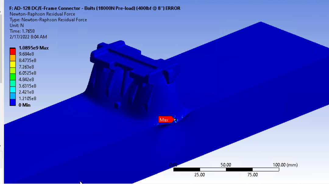
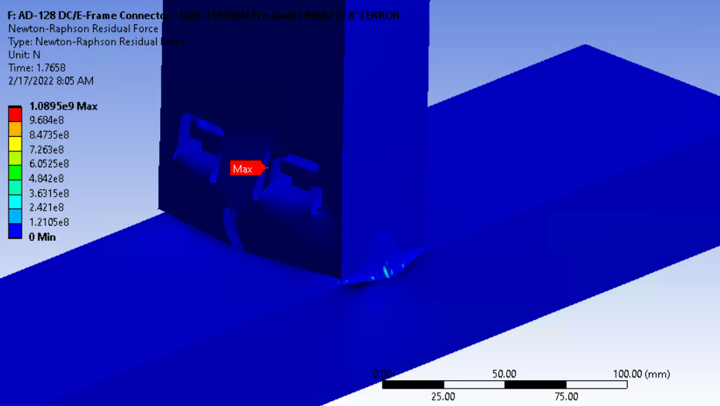
SubscriberHello Peteroznewman So I have not been able to get my solution to converge yet the way that I feel it should. In addition I am not sure how to plot the Newton Raphson residual stress or if the graphics view is the only source of information when the solution does not converge. The results that I am having is the following. See Screen shot. The issue all lies in the pre-load setup and that is behaving in my model. I have no idea why the pre-load is causing this when there should be enough contacts to control this. This is at true scale as well.


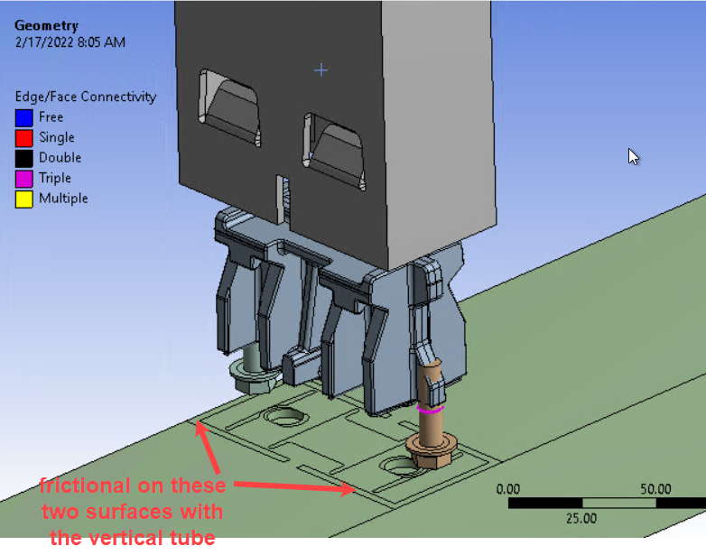
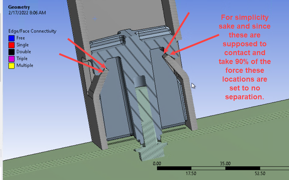
Again here shows the setup that I used and the projections in order to add teh contacts required.


 Thanks again for all the help and if there is additional information that I can provide with regards to contacts please let me know.
Viewing 6 reply threads- The topic ‘Contacts Required for Connector Simulation’ is closed to new replies.
Innovation SpaceTrending discussionsTop Contributors-
4693
-
1565
-
1386
-
1242
-
1021
Top Rated Tags© 2025 Copyright ANSYS, Inc. All rights reserved.
Ansys does not support the usage of unauthorized Ansys software. Please visit www.ansys.com to obtain an official distribution.
-


Ansys Assistant

Welcome to Ansys Assistant!
An AI-based virtual assistant for active Ansys Academic Customers. Please login using your university issued email address.
Hey there, you are quite inquisitive! You have hit your hourly question limit. Please retry after '10' minutes. For questions, please reach out to ansyslearn@ansys.com.
RETRY


