-
-
October 8, 2024 at 6:16 pm
matt
SubscriberI would like some information related to the mixed-dimension 2D/3D analysis that was released in v2019R2. I found a few brief YouTube videos about it and it seems simple to use. However, I have a small test model and for some reason, I cannot set up a contact pair. It continues to give me an error, "The geometry applied to this object is invalid for a mixed dimension analysis." The image below shows my scoped edge on the 2D axisymmetric body, as well as three scoped edges on the 3D multibody part. Can anyone share some feedback as to what I might be doing wrong?
Â
-
October 9, 2024 at 6:49 am
Kaushal Vadnere
Ansys EmployeeÂ
Hi Matt,
Mixed Dimension refers to an analysis with both Solid and Surface/Line bodies grouped under a common Part. From the image you’ve shared, it seems that the surface body is not in the same component as the solid bodies. If you’re using spaceclaim, select all 3 bodies > rmb > move to new component and in properties and change share topology to ‘Group.'Â
-
October 9, 2024 at 12:19 pm
matt
SubscriberMy apologies, but I think you are misunderstanding. At v2019R2, development enabled mixed dimension analysis where 2D and 3D bodies could co-exist in the same analysis.  In other words, a body could be modeled as 2D axisymmetric in the same analysis with other 3D solid bodies. See the image below from "What's New" in v2019R2 Help documentation, where it was released.
-
October 10, 2024 at 9:22 am
Kaushal Vadnere
Ansys EmployeeMy apologies for misinterpreting your question. I tried a simple test case of a camshaft to check the issue. The cam lobe is modelled as 3D body and the shaft is modelled as 2D axisymmetric body.
Are you defining 2D behaviour as '2D axisymmetric' or 'General axisymmetric'? I would suggest you to use 'General Axisymmetric' under the body definitions. Create a new coordinate system with one of the axes aligned with the axis of symmetry and then add General axisymmetric under the symmetry object and scope the new COS to it (see image below, X-axis is aligned with the axis of symmetry). Please refer to this article from Ansys help document regarding general axisymmetry:Â 15.1.4. General Axisymmetric Overview (ansys.com)
Using General axisymmetry, I was able to solve without any errors.
Let me know if this helps.
Thanks. -
October 11, 2024 at 7:17 pm
matt
Subscriber
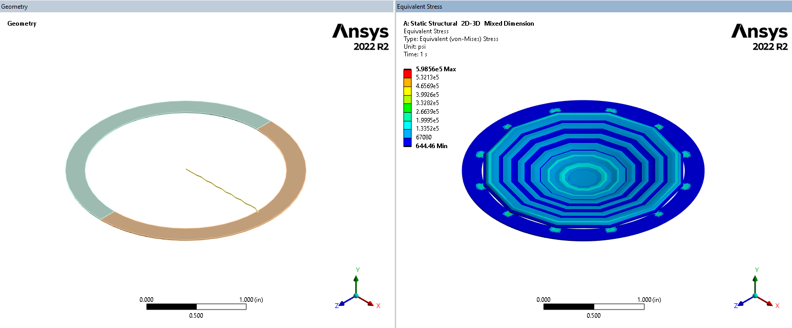
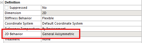
Thank you, this is enough information. I had found an old model on the web from v19.2 when it was a beta feature. In that scenario, "general axisymmetric" was unneeded; i.e., "pure axisymmetric" worked fine in the beta condition. However, I now realize that the fully released feature operates with "general axisymmetric." I definitely have hesitations about it though since the max number of nodal planes in general axisymmetric is 12. And in that case, the interaction with neighboring 3D bodies is only at those 12 planes. Therefore, results can look like the following image, which are very questionable. I think I'm going to stay away from this technology since I don't think it is completely polished yet.
-
- You must be logged in to reply to this topic.
- At least one body has been found to have only 1 element in at least 2 directions
- Script Error Code:800a000d
- Element has excessive thickness change, distortion, is turning inside out
- Elastic limit load, Elastic-plastic limit load
- Image to file in Mechanical is bugged and does not show text
- Help to do quasistatic analysis in static structural module
-
1932
-
823
-
599
-
591
-
366
© 2025 Copyright ANSYS, Inc. All rights reserved.