Ansys Assistant will be unavailable on the Learning Forum starting January 30. An upgraded version is coming soon. We apologize for any inconvenience and appreciate your patience. Stay tuned for updates.
3D Design

3D Design

Topics related to Ansys Discovery and Ansys SpaceClaim.

construction of hyperbola with DesignModeler/SpaceClaim

    • Valeria
      Subscriber

      Hello everyone 


      I need to design a hyperbola with a precise equation into DM or SpaceClaim as Direct Optimization tool is not able to modify the parameters of the hyperbola if I import it from SolidWorks (with parameters imported in Ansys, Direct Optimization still gives error which tells me Geometry update requires user input, but I can't give any input in DM while it's updating).


      Attached is a sketch of my hyperbola (equation y=0.2/(1+29*(x+0.65)). Can anyone tell me how to play with cone parameters to obtain this precisely, if possible? I already tried modify the angle of aperture of the cone and the angle of the plane of intersection, but couldn't obtain the desired curvature.


      Thank you,


      Valeria


    • peteroznewman
      Subscriber

      Hello Valeria,


      What is the range of the X coordinates?


      There may still be a chance to have SW update the geometry. Please put the SW part (or parts and assembly if applicable) into a zip file and attach that after you post your reply and I will see if I can get that working. Also say what version of SW you are using, I have SW2017 installed.


      Regards,


      Peter

    • Valeria
      Subscriber

      Hello Peter,


      thank you for yoru feedback.


      x goes from -1 mm  to 0.75 mm, I have SW 2012-2013


      Valeria

    • peteroznewman
      Subscriber

      Valeria,


      I was able to open your SW file in SW2017 and I see the equation. Which coefficients of x do you want to make parametric?


      Your SW sketch is not fully constrained, meaning when I change the value of 29.32 to other values and back, it does not return to its original shape.


      Please fully constrain your sketch so that it cannot be ruined by parameter changes, and reply with a new zip file.


      Regards,


      Peter

    • Valeria
      Subscriber
      Thank you for your detailed answer. I'd like to vary just d but keep the curvature as it is, meaning I don't want to change 29.32. You mean I should put 29.32 as parameter to fully constrain the sketch?
    • peteroznewman
      Subscriber

      Over what range do you want to vary the d parameter, which is currently at 0.65?


      I have read that a dimension in a sketch is needed to represent the parameter d in the equation curve. Please create a new sketch with a circle with the diameter dimension at the value of 0.65.


      A fully constrained sketch means there are no blue lines, it is all black. If you dimension vertically to one of the blue lines, it will turn black.


      If 29.32 is a constant, leave it a constant.


    • peteroznewman
      Subscriber

      Valeria,


      Here is what I found searching the Internet.  I tried that on your SW part.


      I create a Global Variable "DS_c"


      Then I use that variable in the Curve Equation.


      Unfortunately, when I created a parameter for 29.32, this did not seem to update the geometry.


      There was another page that had a different approach to creating Parameters that also claimed to update, but that was more work and I haven't tried it yet. Have you tried any of these methods?


      Regards,


      Peter

    • Valeria
      Subscriber

      Thank you Peter,


      I want to change lc from 0.5 to 0.8 say, and leave 29 constant as curvature, so it is not necessary to update it.


      I'm afraid I don't fully get why I should draw a circla, isn't it enough to fully constraint skeatch by fixing each line?


    • peteroznewman
      Subscriber

      Good morning Valeria,


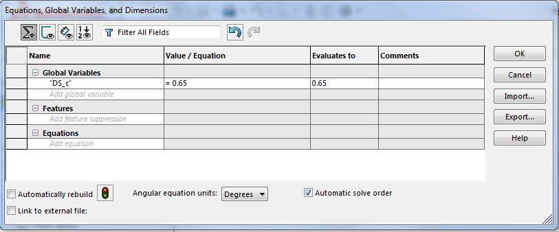
      There is an Ic dimension of 0.65 and there is a value of 0.65 in the curve equation and there is a value of -0.65 in the X1 field.  Do they all change together?  If I type in 0.8 for all, the shape of the sketch is shown below, is this what you want? I don't think so.


      If I change Ic to 0.5 and also the values in the equation curve and X1, the sketch looks like the one shown below.


      Below I added a colinear constraint to the two top horizontal lines, see how the lines turned black?


      Now when I type in 0.8 for Ic and the two values in the equation, I get a very different sketch as shown below.


      Below is all values at 0.5 after the colinear sketch constraint was added. Do you see the importance of a fully defined sketch?


      I'm guessing that the above two sketches are what you want for the extremes.


      Please attach two SW part files (in a zip file), one at 0.5 and one at 0.8 to show me exactly what you want, so I don't have to guess. 


      If you read in detail the last link, and watch the video that was attached, it describes a way to get a Design Study expression into a Curve Equation so that it will update.  That only works if you have a sketch that has a dimension that contains the value you want to use in the curve equation.


      Kind regards,


      Peter

    • Valeria
      Subscriber
      Hello Peter
      I worked it out a bit more. I want to change the length and to do this while maintaining the final height wc=0.01 the curvature (value 29) must change.
      Yes 0.65 is the same value in equation and ranges because it's exactly the length I want to change.
      As you guessed the last two sketches you attached are what I would like.
      I will take a look more attentively at the link you're referring to.
      Many thanks for being so helpful.
      Valeria
    • Valeria
      Subscriber

      Hello Peter, I looked again at the link and video yu suggested (https://forum.solidworks.com/message/757530) but the thing is I don't want any other bodies to be imported (like extra sketches to control the curve) into WB from solidworks CAD and I'm guessing if Direct Optimization would then act on the extra sketch to fix the curve at each desing point? I don't think so, as it works only on what is imported in Geometry of Workbench... What would you say?


      By the way, the global variable way looks more appropriate and I tried to do as follows in SW


      global variable "c"=0.65; global variable "a"=29 and equation given by 


      y=0.2/(1+"a"*(x+"c") with x1=-0.65 (-"c" wouldn't work) and x2=0


      I'm not sure if I should give dimension to Lc in such case as it would be contrained? I give colinear constrain as you suggested and imported everything into Ansys Design Modeler but it reads 65 for "c" instead of "0.65", which is quite strange because all other parameters are imported correctly, and they are decimal as well (SW works with dots whereas DM works with commas). Any suggestion about that? 


      Maybe if I could be able to parametrize the curve in SW with a and c and pass these two as parameters into Design Modeller, then direct optimization would be able to update the curve when giving a,c as input parameters?


      I thank you again for your help


      Valeria

    • peteroznewman
      Subscriber

      Hello Valeria,


      To do shape optimization with SW and WB, you want SW to have a global variable with a DS_ prefix that WB uses to look for the few parameters from the complete set in SW to use. In this case "DS_c" would be used. WB sends a new value for DS_c to SW, which updates the geometry and sends a new solid body back to WB.


      The properties of the Geometry cell in WB limits what is being imported. In your case it would be set to Solids, so no sketches will be imported.


      The first method I tried (without a second sketch) in SW did not update when I changed the value and Rebuilt the model. Try it with the "a" parameter since that is very easy to visually check as you go from a=19 to a=49 that there is a large change in curvature.  But when I edited the value of the Global Variable in the Equations... table and clicked Rebuild, there was no change in shape.  That is why I recommend you try to follow the more complicated second method that requires a second sketch with a dimension on it, and manually build the Parent-Child relationship between the two sketches that triggers the update to happen.


      ANSYS does not respect the regional setting that lets you use a comma as the decimal separator. It was written assuming that the period is the decimal separator.  Change your regional settings to use period as the decimal separator.  That will make "c" come in as 0.65 instead of 65.


      You said that in SW, you couldn't type -"c" in the X1 field.  You can't just type -0.65 if you want that to be a parameter.  The work around is to create a Global Variable "e" that is set equal to -c in the Equations... table. Then you can type "e" in the field for X1.  Or you could just set "c" to a negative value and change the sign in front of "c" in the curve equation.


      You can't overconstrain your sketch, nor do you want it under-contrained. You have to figure out what works and make sure that when you type new values in the Tools > Equations... table in SW, that the shape changes appropriately.


      Regards,


      Peter

    • Valeria
      Subscriber

      Hi Peter,


      thanks for your tips. I'm afraid I have a different version of Windows (I have Windows 10 home) as in regional settings I cannot change number format but just time and other stuff.


      As for variables, I'll try both ways, with or without the additional sketch.


      regards


      Valeria

    • peteroznewman
      Subscriber

      Hello Valeria,


      Your original question was how to construct a hyperbola curve in SpaceClaim. I did some research and found that Equation driven curves were added to SpaceClaim in 2016.  See the Sigma button in the toolbar?  What version of ANSYS are you using?


      Unfortunately, they don't allow [C] to be used in the End definition, so you would have to do some construction to trim off an excess length.


      I don't yet know if these parameters can be used by Workbench to update geometry during a Design Optimization.


      Attached is an ANSYS 19.1 SpaceClaim file.


      Regards,


      Peter

    • peteroznewman
      Subscriber

      For Windows 10, you can change your Regional Settings and use a Period as a Decimal Separator if you click Additional settings...


    • Valeria
      Subscriber

      thank you Peter, in the end I was able to solve it by adding an  additional sketch to control the parameter Lc. The only one last thing which I doubt is how to let DesignModeler "fix" a slice, in the sense that now when it varies the length correctly but I made a slice through a plane parallel to YZ to slice the domain for meshing operation and now this slice moves around like in the photo attached. I'm afraid in this way the remeshing is not very efficient, would you suggest something different?

    • peteroznewman
      Subscriber

      Hello Valeria,


      Create a parameter in DM that is used to locate the Plane used to slice the geometry. That parameter will have the parameter for Lc in it so that the plane and the hyperperbola will move together.  If you need help, attach your Workbench Project Archive .wbpz file and I will demonstrate.


      Regards,
      Peter

    • Valeria
      Subscriber

      Yes it is exactly what I tried to do but can't put Lc inside the parameter which defines the position of the plane in no way. Many errors occur in parameter set when I tried, also because the plane position is in mm whereas Lc is with no unit because imported from SolidWorks.


      I attach my WB, many thanks for your thorough help!


    • peteroznewman
      Subscriber

      Hello Valeria,


      I can't test if my edits are working unless you also provide the SW part file that is linked to this WB file.


      Regards,


      Peter

    • Valeria
      Subscriber

      Hello Peter,


      I managed to work this out by putting (-"P2"*1[mm]-0.03) inside the plane4 definition and to move it together with Lc, as suggested elsewhere 


      thank you for your help


      Valeria

    • peteroznewman
      Subscriber

      Hello Valeria,


      I'm glad it's working for you now.


      It would be helpful if you attach a zip file with the .wbpz file and the SolidWorks part file in it so that some other student with a similar need might find a working example they can follow.


      Regards,


      Peter

    • Valeria
      Subscriber

      yes sure, good idea


      attached both WB file and SolidWorks 


      Valeria

    • Valeria
      Subscriber

      solidworks part could not be attached because "extension not allowed" message appears, yet I already attached a part with same format before

    • peteroznewman
      Subscriber

      Put the solidworks part file into a zip file, then you can attach.  Thanks.

Viewing 23 reply threads
  • The topic ‘construction of hyperbola with DesignModeler/SpaceClaim’ is closed to new replies.
[bingo_chatbox]