-
-
September 30, 2023 at 12:15 am
-
September 30, 2023 at 10:58 am
peteroznewman
SubscriberMesh the rectangle with a single linear element and you will get straight edges.
-
September 30, 2023 at 1:31 pm
jccubisino
SubscriberThank you Peter for your quick reply. I am afraid that if I proceed in the way suggested above, the precision of the results would be affected since the plate is in fact a 1500 x 500 mm stiffened plate. Could you please give me any other idea? Thank you.
-
-
September 30, 2023 at 3:09 pm
peteroznewman
SubscriberWhat are the true boundary conditions and loads applied to it.
How is it possible that those loads and boundary conditions result in straight edges?
If the true deformation results in non-straight edges, why would you want to enforce a non-physical boundary condition?
-
September 30, 2023 at 8:30 pm
jccubisino
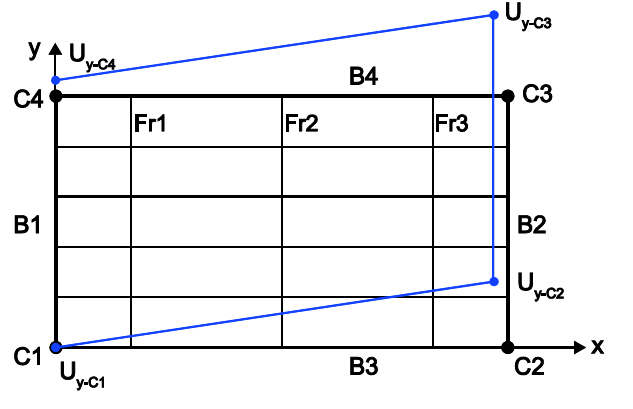
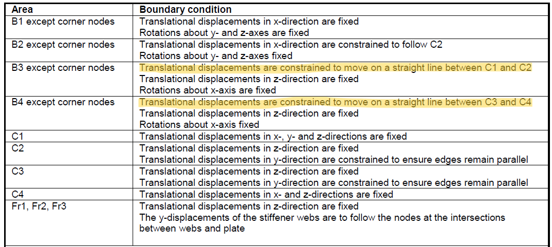
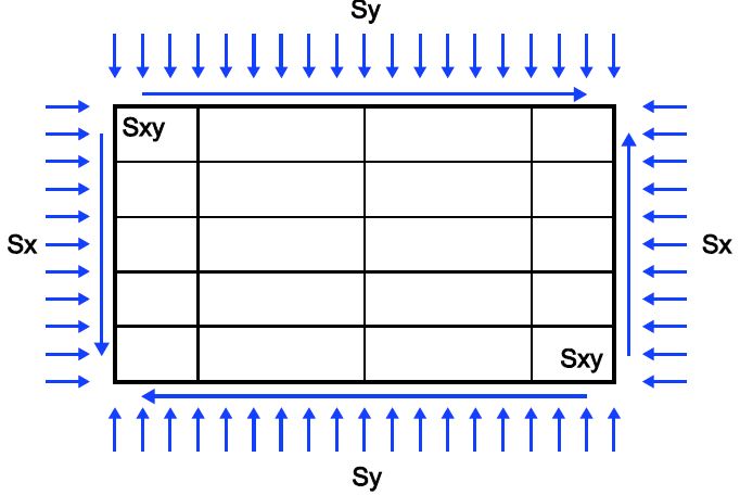
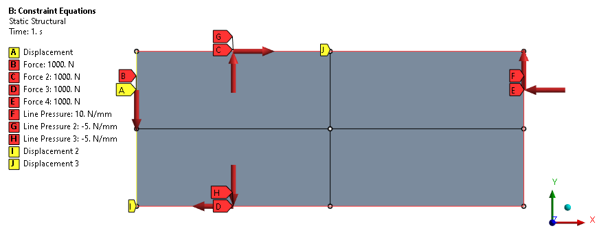
SubscriberDear Peter, boundary conditions and loads are shown in pictures below (they are referred to the 2nd picture above). Boundary conditions are established by a regulatory body in ship structrural certification therefore I am not sure about the background to require straight edges but usually is because the panel is sorrounded by many other panels, therefore edges are assumed ideally straight.
I tried using simetric conditions in edges B3 a B4 but, in this case, edges can not be loaded. I hope this helps. Thank you in advance.
-
-
October 1, 2023 at 1:43 pm
peteroznewman
SubscriberUse Constraint Equations.
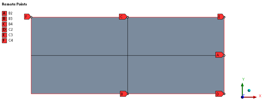
First in geometry, split the surface to create a vertex where you need to control the side of the shape.
In Mechanical, create Remote Points at all the corners and sides that need to be controlled. Mesh with one linear element per body.
Next create Constraint Equations to force the mid point to stay halfway between the corners in the X and Y directions. For example, this equation forces B2 to be halfway between C2 and C3 in the X direction. I used a total of seven Constraint Equations.
Apply other loads and boundary conditions that are needed to deform the part.
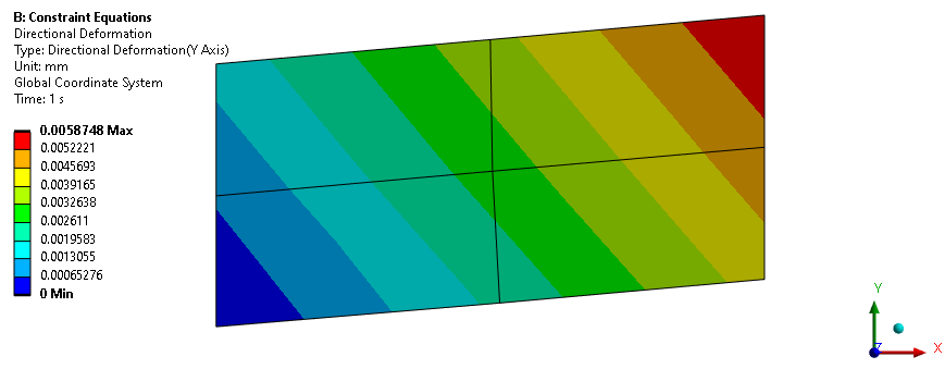
The result is the sides remain straight and parallel.
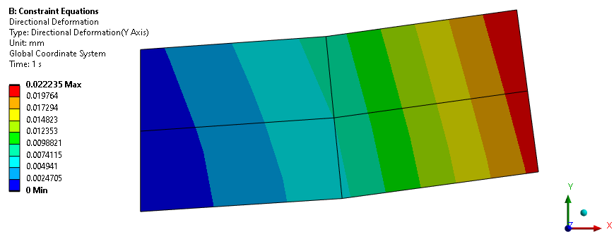
Note that Constraint Equations add stiffness to the part compared with having no constraint equations. Observe below how much larger the deformation is under the same loads without the constraint equations.
Good luck!
-
October 3, 2023 at 1:58 am
jccubisino
SubscriberThank you Peter for your help and your time. Your ideas are allways really appreciated.
Best Regards
-
-
- The topic ‘Constraint in Line’ is closed to new replies.


-
5089
-
1823
-
1387
-
1248
-
1021

© 2026 Copyright ANSYS, Inc. All rights reserved.


