We have an exciting announcement about badges coming in May 2025. Until then, we will temporarily stop issuing new badges for course completions and certifications. However, all completions will be recorded and fulfilled after May 2025.
General Mechanical

General Mechanical

Topics related to Mechanical Enterprise, Motion, Additive Print and more.

Connection issue – Internal solution magnitude limit/Pivot error

    • ianyylai
      Subscriber

      Hello all,

      I am trying to run simulations on a model that I converted them into shells and beams (mostly because I want to have more elements under the STudent License limit), and the dimension ratio of those parts make it quite reasonable to do so. It is an assembly file drawn in SOlidworks. Everything went well when the connection between the end vertice of the beam and the face of the plate below is set as "Bonded". I want to connect them through other means but any other kinds of connections cause an error.

      "A solver pivot warning or error has been detected in the UZ degree of freedom of node 24336 located in SYS-1\Beam (Extracted Profile1). This is usually a result of an ill conditioned matrix possibly due to unreasonable material properties, an under constrained model, or contact related issues.  Check results carefully. You may select the offending object and/or geometry via RMB on this warning in the Messages window."

      I have tried to change the connection settings, loading magnitudes, and the error kinda changed into the following one:

      "An internal solution magnitude limit was exceeded. Please check your Environment for inappropriate load values or insufficient supports.  Please see the Troubleshooting section of the Help System for more information."

      I know other people in the forum have similar issues, but the differences in model geometry make it quite difficult to utilize the same solutions. Can anyone provide some insight on this? Thanks!

    • Rajesh
      Subscriber

      Hello ianyylai, maybe try to use MPC formulation in this connection and check in Contact Tool if the connection is closed. It should solve your problems. If you want you can also turn on Weak Springs just for a single solve and after solve you will be able to check on deformation contour plot where occurs the lack of required connection. Then change options for that connection solve again with weak springs and judge if its okay. If okay solve once again, but with Weak Springs turned OFF. Then do final check if its okay.

    • peteroznewman
      Subscriber

      Please show where the model has a Fixed Support and what the condition is on the other end of the beams.

    • ianyylai
      Subscriber

      Hi, when I set the formulation to MPC under Frictional contact, the system highlights the row of "Formulation" and shows a question mark in front of "Contacts", like what you would get in "Geometry" without defining a material. I tried and found that this is the case for Frictional, Frictionless, and Rough. It's fine for Bonded and No Seperation but those 2 are not what the contacts should be. Any thoughts on that?

      On the other hand, the following picture indicates the boundary conditions of the model for your information. Thanks!

    • Rajesh
      Subscriber

      OK in Home Tab you have button, named: "Show Errors". Turn it ON and click Solve. After that, try to check Message tab (in the bottom part of graphic window). Then please show errors that appears, especially that one related with a question mark.

    • peteroznewman
      Subscriber

      Hello ianyylai,

      You have a beam inside a tube. You want the sides of the tube to hold the beam from falling over. Therefore, you have to add Frictional Contact between the beam and the sides of the tube. Without contact, there is nothing preventing the beam from moving in X or Z (assuming Y is vertical) or tipping over.

      Also, if you don't have Standard Earth Gravity turned on, the beam is not pushing down on the surface where you have defined contact.

    • ianyylai
      Subscriber

      Hi, as attached is thepicture of connection that makes the error "BONDED or NO SEPARATION type required for this contact configuration" appears. It is under Frictional, which I think is the problem. I read from a few articals saying Normal Langrange should be used for non-linear contacts. But when I use Normal Langrange, the error "An internal solution magnitude limit was exceeded. (Node Number 24274, Body SYS-1\Beam (Extracted Profile1), DOF UZ) Please check your Environment for inappropriate load values or insufficient supports.  You may select the offending object and/or geometry via RMB on this warning in the Messages window.  Please see the Troubleshooting section of the Help System for more information." returns. I am unable to use Normal Lagrange so far.

      And for creating a Frioctional Contact between the beam and the sides of the tube, I just added it! Thanks! Though the simulation couldn't run anyway because of the connection issue.

    • peteroznewman
      Subscriber

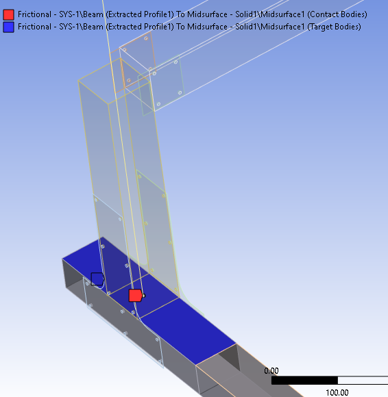
       I suggest you use No Separation for contact between the vertex and the horizontal surface. That seems reasonable. 

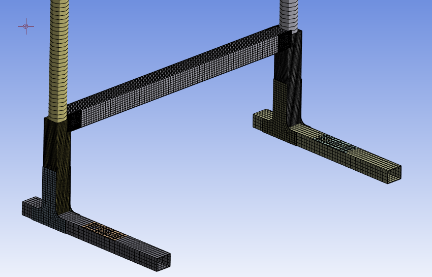
      Static Structural models don't like to start when there is zero stiffness in any of the 6 directions (3 translations, 3 rotations) of one body relative to another (or ground).  For example, if the diameter of the beam is 50 mm and the internal dimension of the square tube is 52 mm, then there is 1 mm of clearance on each side of the beam if it is positioned in the center of the tube. That means the beam has zero stiffness in 5 directions (since the vertex on the bottom face takes care of Uy).

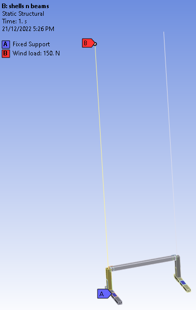
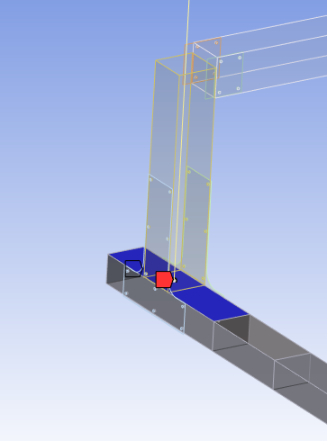
      The corrective action is to tilt the beam so the beam is in the -X, -Z corner of the tube at the bottom and at the +X, +Z corner of the tube at the top of the tube, and the Wind Load must be in a direction that includes positive forces in the +X and +Z direction so that it continues to push the beam into those two corners.  Now the beam has stiffness in 6 directions. Rotation about Y is taken care of by the Coefficient of Friction.

      If that seems like a lot of work, you can simply make the beam have the same dimension as the ID of the tube. But, you must insert a Contact Tool under the Connections folder and Generate Initial Contact Status. The contact must be Closed.  If it is Near Open, it might have a tiny gap. That is still zero stiffness. Increase the beam diameter by a tiny amount until the contact becomes closed. The benefit of this approach is that the wind load can be in any direction.  With a tilted beam, if the wind load was to push the beam away from the corners it was nested in, that might cause the solution to fail.

    • ianyylai
      Subscriber

      HI. Thanks for the detailed explanation, I will definitely try it! Since you mentioned the problem of the Direction of the stiffness problem, do you think it is the reason the solution failed when the connection was not Bonded? SInce only when Bonded, the beam would have all 6 directions of stiffness taken care of (since all 6 are fixed). And after I generate a No Separation, how do I make the beam have the same dimension as the ID of the tube?

      On the other hand, do you know what's the issue with Normal Lagrange that I can't use it? Thanks a lot!

    • peteroznewman
      Subscriber

      You just make the beam have the same dimension as the ID of the tube. This is independent of the No Separation contact.

      Bonded contact fixes all the freedom between the beam and the tube.

      I don't know why you can't use Normal Lagrange. It would be some mathematical reason. Why do you want to use it instead of the Program Controlled setting or any other formulation?

    • ianyylai
      Subscriber

      Hi peter, I was under the impression that Normal Lagrange and MPC should be used where possible. Just some content I found online. It was said NL provides higher accuracy.

    • peteroznewman
      Subscriber

      Ansys uses Augmented Lagrange for as the Program Controlled default, so I would say that Ansys considers that the best first try for Frictional Contact.  For Bonded Contact, I always want to use MPC because I can see the Connection Elements after it has solved to verify which nodes are connected.

    • ianyylai
      Subscriber

      Hi, I hope someone is still here since I found something new. When I turn on Weak Springs I seem to find where the problem is. It is a newer design of the model but the loadings and overall functions are pretty much the same. The beam seems to have ignored my bonded contact I applied onto the circular surfaces around the bolt holes (one in the middle of the horizontal plate ad one inside the beam)

      When I was forced to bond the plain surfaces instead, the beam does move with the plate but then the firctional contact was ignored. I applie them between the faces of rectangular parts under the plate and the vertical square tube. The system completely ignored them and let me penetrate.

      The fixed support and loadings are identical as mentioned above, and a newer illustration of the model is attached as below. Does anyone know what to do with it?

    • ianyylai
      Subscriber

      The problem stays even when I change the connections to Bonded between the side faces of the vertical tubes and the rectangular parts. That looks completely off.

    • peteroznewman
      Subscriber

      I think you will have more success if you convert the tubes from solids to midsurface bodies. They will perform better in this model.

    • peteroznewman
      Subscriber

      Bumping this thread to the top.

      I think you will have more success if you convert the square tubes from solids to midsurface bodies. They will perform better in this model.

Viewing 15 reply threads
  • The topic ‘Connection issue – Internal solution magnitude limit/Pivot error’ is closed to new replies.