TAGGED: 2020r2, contact, mechanical
-
-
April 15, 2025 at 9:16 am
35020306
SubscriberDear all. I am currently modeling a suspension bridge in Mechanical and I have run into some issues related to connections. For the sake of troubleshooting the problem, I have surpressed all other structures except for the main suspension cables and the tower structures. I figured that the problem must lie in the connections between the main cables and the tower structures. I have tried using Node Merge based on my previous experience in modeling a cable-stayed bridge, however the analysis remains unstable with the results showing solver pivot errors. If there's anyone who has had the experience in modeling a suspension bridge in Mechanical, I would like to ask for your advice. One solution I came across is to use the APDL command "CP" to couple the DOFs of the cable and the tower, however I wonder if I could do it through GUI which would be easier.
-
April 15, 2025 at 10:26 am
Akshay Singh
Ansys EmployeeTry a Modal Analysis first with only the cables and towers. This can help identify if the instability is due to missing constraints or incorrectly modeled connections.
Use Joint objects (under "Connections") and choose an appropriate joint type:
Revolute, Universal, etc. depending on your idealized boundary behavior.
You can mimic the APDL
CPcommand by using:Remote Points connected to both cable and tower faces or vertices.
Set the remote point behavior to Coupling, then select the DOFs you want to couple (e.g., UX, UY, UZ).
12.1. Remote Point Application
-
April 17, 2025 at 9:01 am
35020306
SubscriberThank you. I finally got it working with Remote Points.
-
April 15, 2025 at 10:51 am
peteroznewman
SubscriberDear Audy,
A diagnostic test that helps reveal if any component in an assembly is not connected to other components and if the structure as a whole has sufficient supports to ground is to run a Modal analysis. Drag a Modal analysis out of the Workbench Toolbox and drop it on the Model cell of the Static Structural analysis. Drag any Fixed Supports or other required supports from the Static Structural branch and drop them on the Modal branch in the Outline. Under Analysis Settings, change the Max Modes to find to 20 instead of 6.
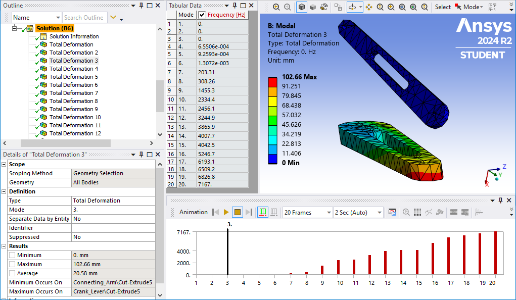
After the Modal analysis is solved, you can see in Tabular Data 20 rows. If any of the Frequencies show a value near zero, that is evidence of a part not properly connected. If the part is completely unconnected, there will be 6 modes with near zero frequency. Click on the Mode label to highlight all modes then right click and select Create Mode Shape Results. Under Solution, right click to Evaluate All Results.
Click on each Total Deformation result with a near zero frequency. Graphically, the unconnected part will reveal itself. You can animate the result and the part will float around the fixed parts. In the Details window, the name of the part with the maximum deformation will be given.
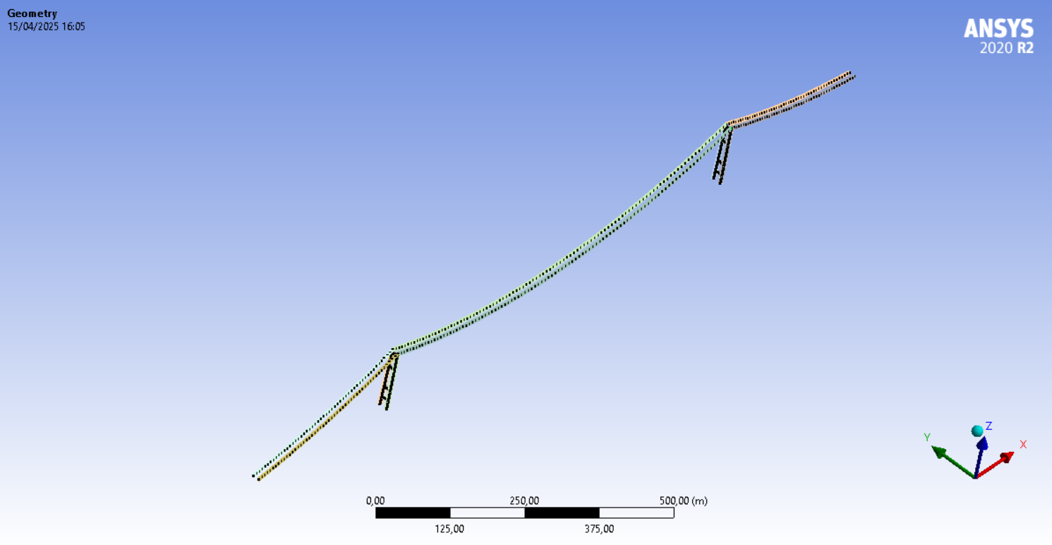
It’s also possible that all parts are connected, but the solver pivot error is due to a massive ratio in the stiffness matrix. For example, the cable is free to swing laterally with almost zero stiffness. That could be diagnosed by adding a Y=0 displacement boundary condition to all the nodes of the cables. What kind of element type is the cable meshed with? Is it a Beam188, Link180 or Cable280 element type?
Under Analysis Settings, do you have Large Deflection turned on? That is required to allow tension in the cable to build up when the Standard Earth Gravity load is present. Another common part of the workflow of cable stayed bridge models is the difficulty in achieving convergence in the nonlinear solution. Typically, the use of the INISTATE command is needed to pretension the cable so that when the solver applies gravity, the elements are close to being in equilibrium.
Regards,
Peter-
April 17, 2025 at 9:18 am
35020306
SubscriberThank you for your suggestions Peter. I checked that the cables are meshed using LINK180 element with tension only behavior. I managed to do a successful static analysis by creating coupled remote points between the cables and the towers and using the INISTATE command to give some level of pretension force to the cables.
My next step will be to connect the main suspension cables to the deck using suspender cables. If I may ask one more question, what do you suppose to be the most efficient way to connect the suspender cables with both the main suspension cables and the bridge deck? Can I use Node Merge in this case or should I use the coupled remote points as suggested by Akshay?
-
-
April 17, 2025 at 6:57 pm
peteroznewman
SubscriberIt's going to be less work to use Node Merge so try that first.
-
April 28, 2025 at 6:46 am
35020306
SubscriberI’ve tried connecting all the elements with Node Merge and I have managed to do modal analysis successfully. However, when I tried to do Static Structural analysis, the analysis gave the following error messages :
*** WARNING *** CP = 26.312 TIME= 13:28:45
There is at least 1 small equation solver pivot term (e.g., at the UY
degree of freedom of node 11511) which may indicate a numerically
unstable model. Please check your results carefully.
*** ERROR *** CP = 26.344 TIME= 13:28:45
The value of UY at node 11486 is 1.232991722E+12. It is greater than
the current limit of 1000000 (which can be reset on the NCNV command).
This generally indicates rigid body motion as a result of an
unconstrained model. Verify that your model is properly constrained.
*** ERROR *** CP = 26.344 TIME= 13:28:45
*** MESSAGE CONTINUATION —- DIAGNOSTIC INFORMATION ***
If one or more parts of the model are held together only by contact
verify that the contact surfaces are closed. You can check contact
status in the SOLUTION module for the converged solutions using
CNCHECK.
*** ERROR *** CP = 26.344 TIME= 13:28:45
*** MESSAGE CONTINUATION —- DIAGNOSTIC INFORMATION ***
Rigid body motion can also occur when net section yielding has
occurred resulting in large displacements for small increments of load
or when buckling has occurred. You can plot the time history curve
for node 11486 in the UY direction to check for stiffness (slope of
the curve) approaching zero.
*** WARNING *** CP = 26.344 TIME= 13:28:45
The unconverged solution (identified as time 1 substep 999999) is
output for analysis debug purposes. Results should not be used for
any other purpose.
R E S T A R T I N F O R M A T I O N
REASON FOR TERMINATION. . . . . . . . . .DOF LIMIT EXCEEDED
FILES NEEDED FOR RESTARTING . . . . . . . file0.Rnnn
file.ldhi
file.rdb
TIME OF LAST SOLUTION . . . . . . . . . . 0.45000
TIME AT START OF THE LOAD STEP . . . . 0.0000
TIME AT END OF THE LOAD STEP . . . . . 1.0000
ALL CURRENT ANSYS DATA WRITTEN TO FILE NAME= file.db
FOR POSSIBLE RESUME FROM THIS POINT
NUMBER OF WARNING MESSAGES ENCOUNTERED= 5
NUMBER OF ERROR MESSAGES ENCOUNTERED= 6The total deformation at the end of the analysis gave the following results:
I wonder if this was caused by the cable not connected correctly.
-
April 28, 2025 at 11:25 am
peteroznewman
SubscriberYes, it looks like the cable is not connected correctly. Please show the results of your Modal Analysis.
-
- You must be logged in to reply to this topic.
-
4597
-
1495
-
1386
-
1209
-
1021
© 2025 Copyright ANSYS, Inc. All rights reserved.


