TAGGED: cable, Graphics issues, hydrodynamic, static-structural, visualization
-
-
February 27, 2025 at 12:12 pm
karim.el-ghamrawy
SubscriberHello,
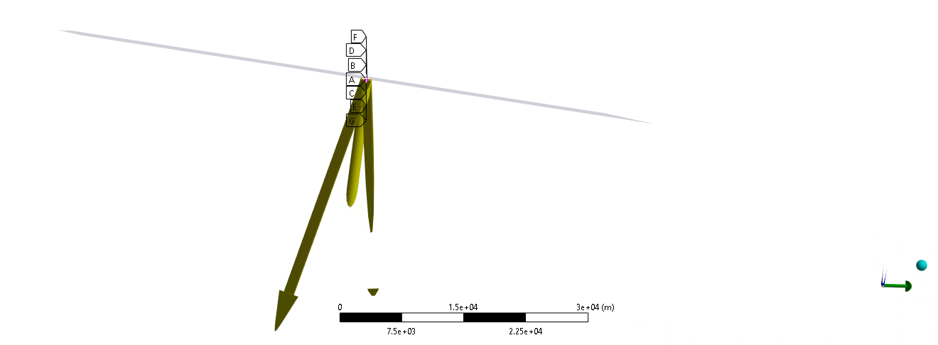
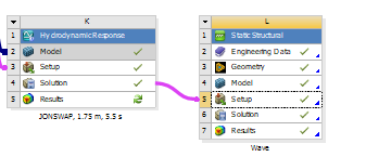
I am connecting a hydrodynamic analysis to a static structural as shown in the following figure.
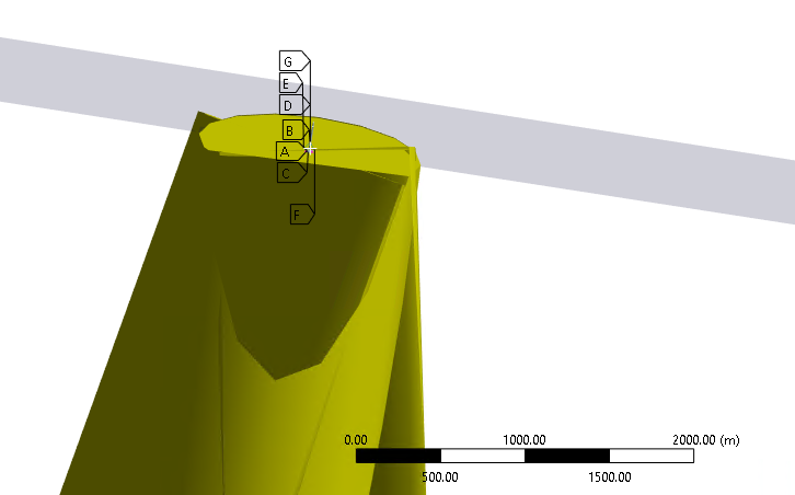
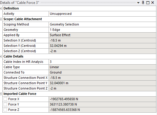
In mechanical, I am adding a hydrodynamic pressure object from the hydrodynamic ACT. Pressure loads are transferred correctly and checked with HR module. I am also adding cables to account for the forces holding the structure. The issue is the following figure, where the arrows are huge compared to the structure knowing that the structure is 200m tall. As shown in the figure below, the structure disappears inside the arrows. Any idea why this is happening? It is also observed that the arrows disappear and appear if I try to rotate the structure. The triad also is disappearing. As shown from the ruler at the bottom, I had to zoom out a lot to see the arrows. The maximum force in each cable in the Z direction is around 18MN and the structure weight is around 4000 tonnes.
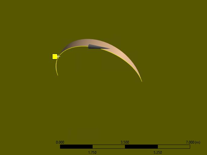
In the following figure, I am showing the edge I am scoping the cable force to. It is a circular edge with 5m diameter. is it wrong to scope to an edge?
Thank you in advance
-
February 28, 2025 at 1:47 pm
Mike Pettit
Ansys EmployeeHello,
This is a bug - I will make sure this is corrected for the next release. The problem is that the scale of the arrow showing the imported cable force is based on the X/Y dimensions of the structure, and its mass (i.e. it does not account for the Z dimension). If your case you have a big force acting on a (laterally) small structure, so the arrows are oversized.
The arrows disappear as you rotate because there is an invisible graphics bounding box in Mechanical, also based on the structure dimensions. As the arrow leaves the box it gets cut off in the display.
Both of these issues are only graphical - the loads will still be applied to your structure as normal. Please do let me know if you have any other issues.
Mike
-
February 28, 2025 at 1:49 pm
Mike Pettit
Ansys EmployeeSorry, to answer your other question - there's nothing wrong with scoping to an edge. The load will be evenly distributed around the circumference of the cylinder.
Mike
-
February 28, 2025 at 2:01 pm
karim.el-ghamrawy
SubscriberThank you for your response. Ok this is clear. I must mention that this is in 2023R1. Hopefully it has been resolved in later versions.
-
- You must be logged in to reply to this topic.


-
2778
-
965
-
841
-
599
-
591

© 2025 Copyright ANSYS, Inc. All rights reserved.

