-
-
January 20, 2024 at 3:47 pm
Prahasith Karimilla
SubscriberHello Fam,
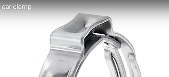
I am trying to simulate the following application:
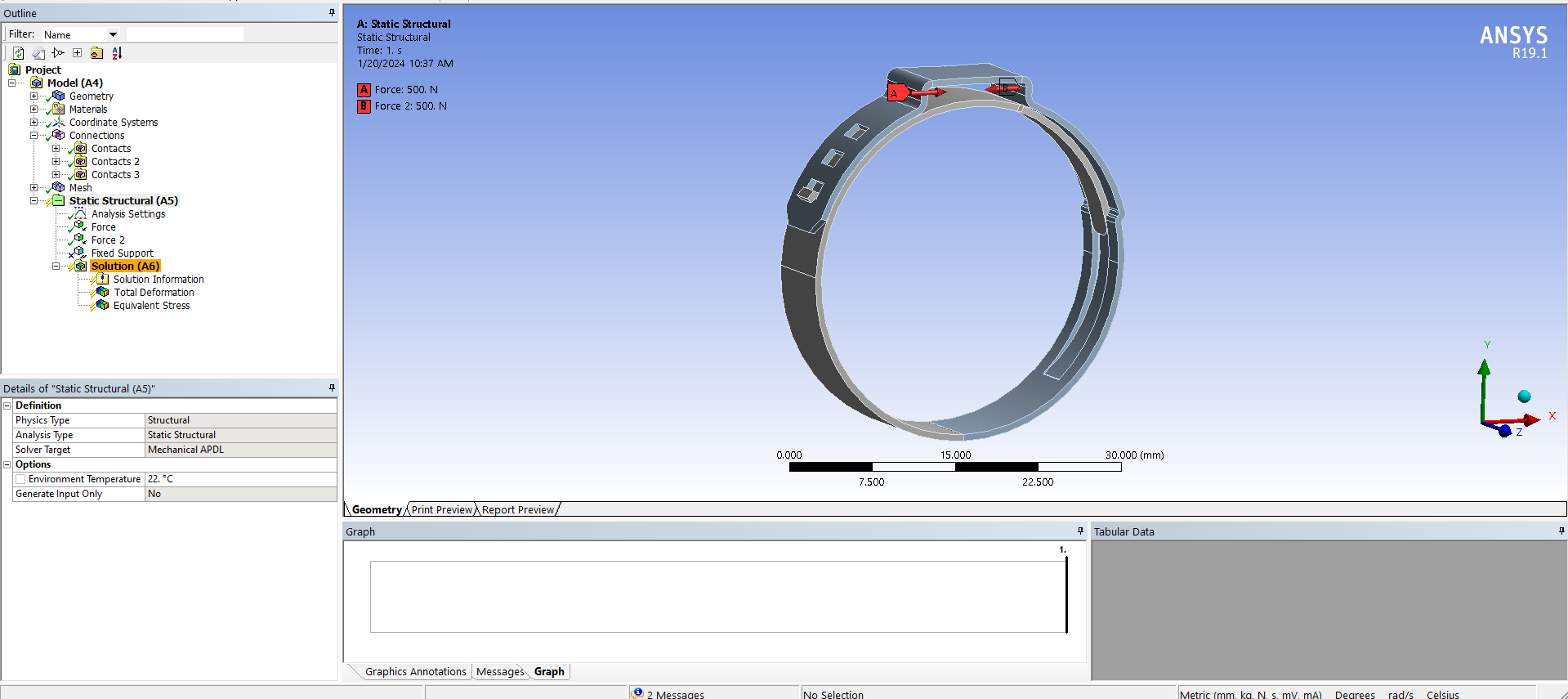
?si=MehtY-6QDuf8FXG1I modeled the clamp as shown below. Now, I am confused about what boundary conditions to use to get the correct simulation results. Can anyone please help me get an idea about what I can do? Are there any additional settings that I need to use? Anything is appreciated, Thank you!
-
January 20, 2024 at 4:04 pm
peteroznewman
SubscriberFirst, go back into the CAD system and add the dimple in the flat top of the ear. That is an important feature that you left out.
While you are in CAD, create the pincer tips which can become ridid bodies in the simulation. You will use those with an enforced displacement boundary condition to squeeze the ear, since you don't know the force needed to deform the ears, but you can estimate the displacement.
Finally, create the tube for the clamp to squeeze against.
-
January 20, 2024 at 4:11 pm
Prahasith Karimilla
SubscriberHello Peter,
Thank you! I have the model with a dimple on it already, I did use that but the results were not convincing, so I thought I would try on a simpler model first.
Your idea seems good but adding the pincer tips and a tube would significantly increase the computational effort right? I don't think my current setup can handle that, though I will try!
-
-
January 20, 2024 at 4:43 pm
peteroznewman
SubscriberYes, a model with a lot of frictional contact will significantly increase the computational effort, but it is required to accurately simulate what is happening. Computational effort will affect the time it takes to solve, so your current setup can handle that. Using rigid bodies for the pincer tips and the tube will have a minimal increase in node and element count.
Add a plane through the center of the tube at the center of the width of the clamp. Split all the bodies and delete the back half of all those pieces. Use a Symmetry boundary condition on all the cut faces. That will free up half the node and element count if you need a finer mesh later and it will cut the computational effort in half. That will also allow the tube to remain flexible instead of being a rigid body.
-
February 7, 2024 at 5:37 am
Sri Harsha Kallakuri
SubscriberHello Peter,
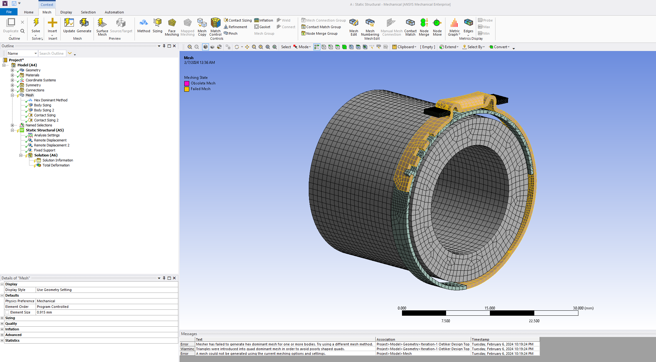
Thank you very much for your insights. We have been trying to solve the model as you said (symmetry). The computational time has increased significantly and the solution is not converging 100%. We have tried increasing the mesh size, but the mesh (Hex Dominant) itself is not generating properly. Could you please help us? Do you think partitioning the model can help?
Thank you.
-
February 7, 2024 at 3:35 pm
peteroznewman
SubscriberYou need to mesh the clamp with 8 linear hex elements through the thickness of the clamp in the zone around where the plastic deformation is occuring. Do not use Hex Dominant. You must use Sweep to create cube-shaped elements through the thickness. This will require that you split the clamp into many six-sided pieces so the Sweep mesher will work. You must use the Share button on the Workbench tab in SpaceClaim to have the mesh on those pieces to be connected. You don't want to have any Bonded Contact in the region of plastic deformation. If that doesn't mesh cleanly, try to Unshare, and use a Node Merge in Mechanical to have the mesh connected instead.
It will be costly to carry an 8-element, through-thickness hex mesh around the full circumference. Split the clamp horizontally and create a midsurface of the lower half of the clamp. That can be meshed with shell elements to reduce the computational effort.
-
February 7, 2024 at 4:03 pm
Sri Harsha Kallakuri
SubscriberThank you for the quick reply. We will try.
-
March 23, 2024 at 4:10 pm
Sri Harsha Kallakuri
SubscriberHello Peter,
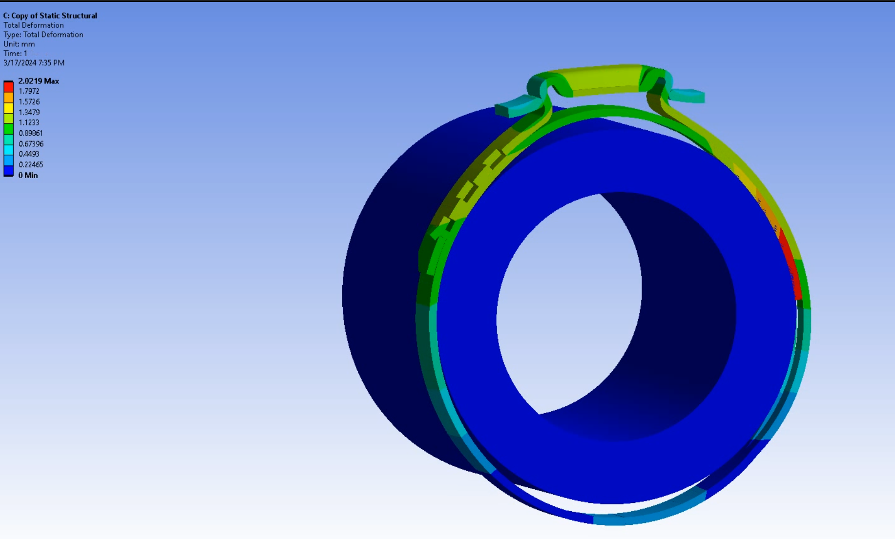
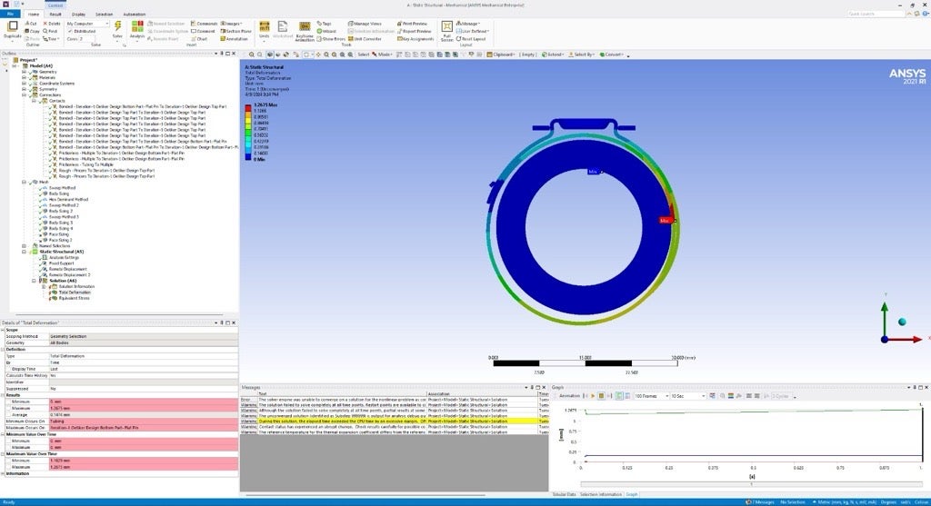
I hope you are doing well. We have done exactly what you have said. After some trial & error, we have got the correct plastic deformation and simulation at the ear but not completely. Here is the 7mm displacement on the pincers in the image. If we increase the displacement, the pincers contact with the ear is getting disconnected. What should we do to achieve complete crimping of the ear? I have also observed in the attached image that the pincers itself getting bent. Should we design actual hook type pincers?
Please help us.
Thank you
-
March 23, 2024 at 5:07 pm
peteroznewman
SubscriberI would like to see the animation of this simulation. Mechanical can write out an .mp4 file of the animation. You can either upload that file to a file sharing site such as Google Drive or you can upload the animation to YouTube. In either case, put a link to the animation in your reply.
-
March 23, 2024 at 5:30 pm
Sri Harsha Kallakuri
SubscriberHere is the video link https://drive.google.com/file/d/1-UYR3M2GWbPGLgWyqcGuxXtL8ghD8R6P/view?usp=sharing
-
March 23, 2024 at 5:41 pm
Sri Harsha Kallakuri
Subscriber -
March 23, 2024 at 6:28 pm
Prahasith Karimilla
SubscriberPlease ignore the previous links, we increased the frames and uploaded better videos in below link-
-
March 23, 2024 at 6:59 pm
peteroznewman
SubscriberIt would be better if the Pincers are changed to be Rigid Bodies so that they do not bend. A change like that can require other changes in the model to accomodate the rigid bodies. An easier way may be to edit the material of the pincher tips and add 00 to the end of the Young’s Modulus, making it 100 times stiffer.
It seems that the pipe could be a larger diameter so that it makes contact at 3 points around the clamp. It seems there is a lot of clearance between the pipe and the clamp.
-
March 23, 2024 at 7:47 pm
Sri Harsha Kallakuri
SubscriberWe will change the pincers to rigid as mentioned. As far as the tubing and the clamp size are concerned, I have designed these based on a real problem I have encountered at my work. We have observed a leakage in one of our Bio-process tubing assemblies. The fluid inside the tubing flows at 35 psi (high pressure for this application). I have primarily identified the cause of the leakage as
- Less Hardness of the Hose (silicone tubing) - The high pressure fluid is making the tube bulge and open a gap for fluid to escape
- Improper selection of oetiker clamp (Bigger size chosen) - The clamp is not properly compressing enough the thickness of the tubing
My intension on this project is to first simulate the crimping of the oetiker clamp (on a hose) and then perform a CFD analysis with 35 psi to see how the fluid is exerting the pressure on the hose and clamp and how the clamp is behaving.
The tube and oetiker size combination I have taken in this project are practically showed no leakage in our testing.
I hope this gives clarity on our intension of doing this study.
-
March 23, 2024 at 7:56 pm
peteroznewman
SubscriberI understand. Mechanical has an excellent capability to evaluate fluid penetration of a seal due to applied pressure. You do not need a CFD analysis, you do it in Mechanical. Read this discussion. Take this free course.
-
March 23, 2024 at 8:11 pm
Sri Harsha Kallakuri
SubscriberThank you! Ill go through it.
-
April 1, 2024 at 2:24 am
Sri Harsha Kallakuri
SubscriberHello Peter,
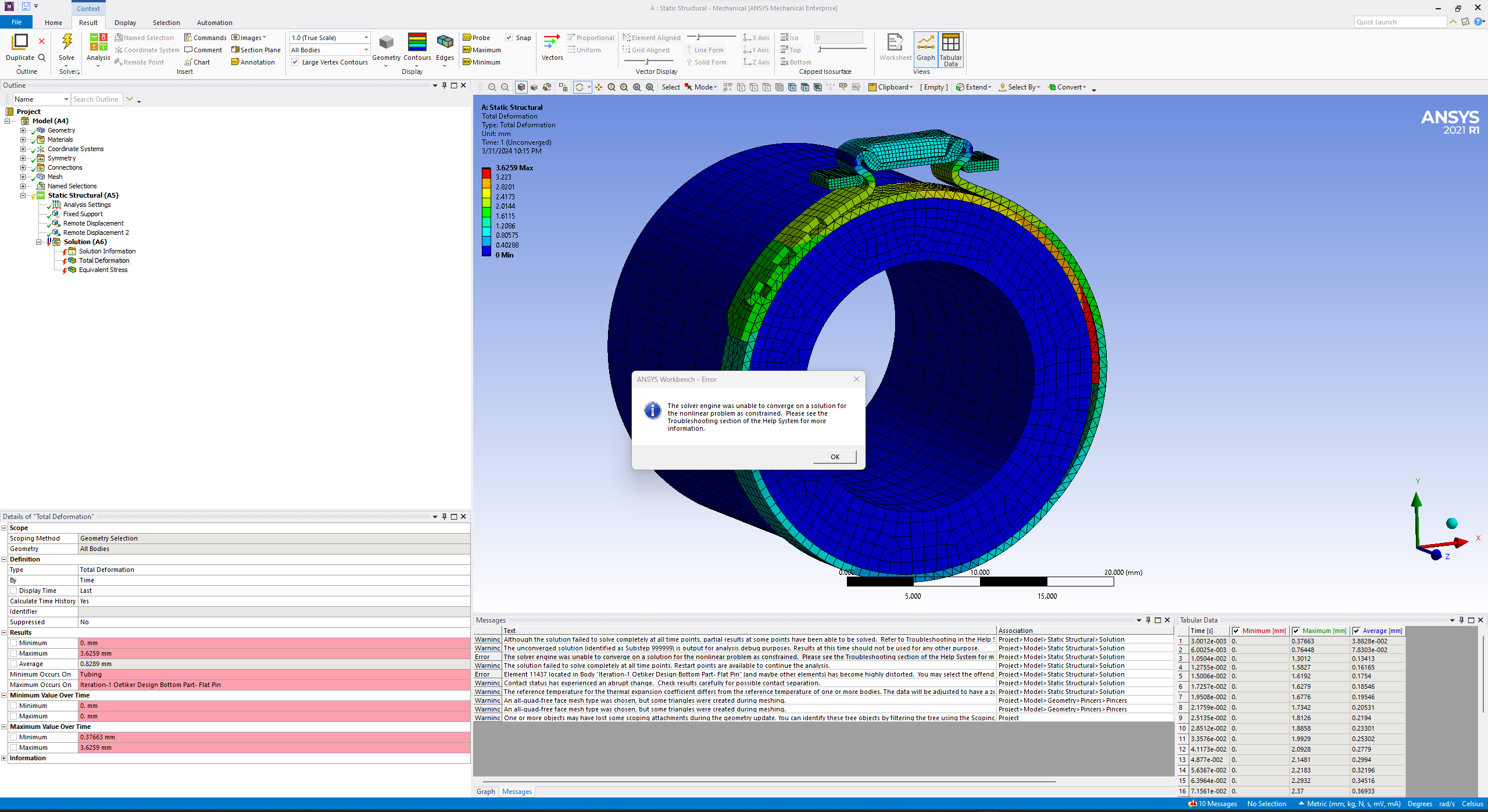
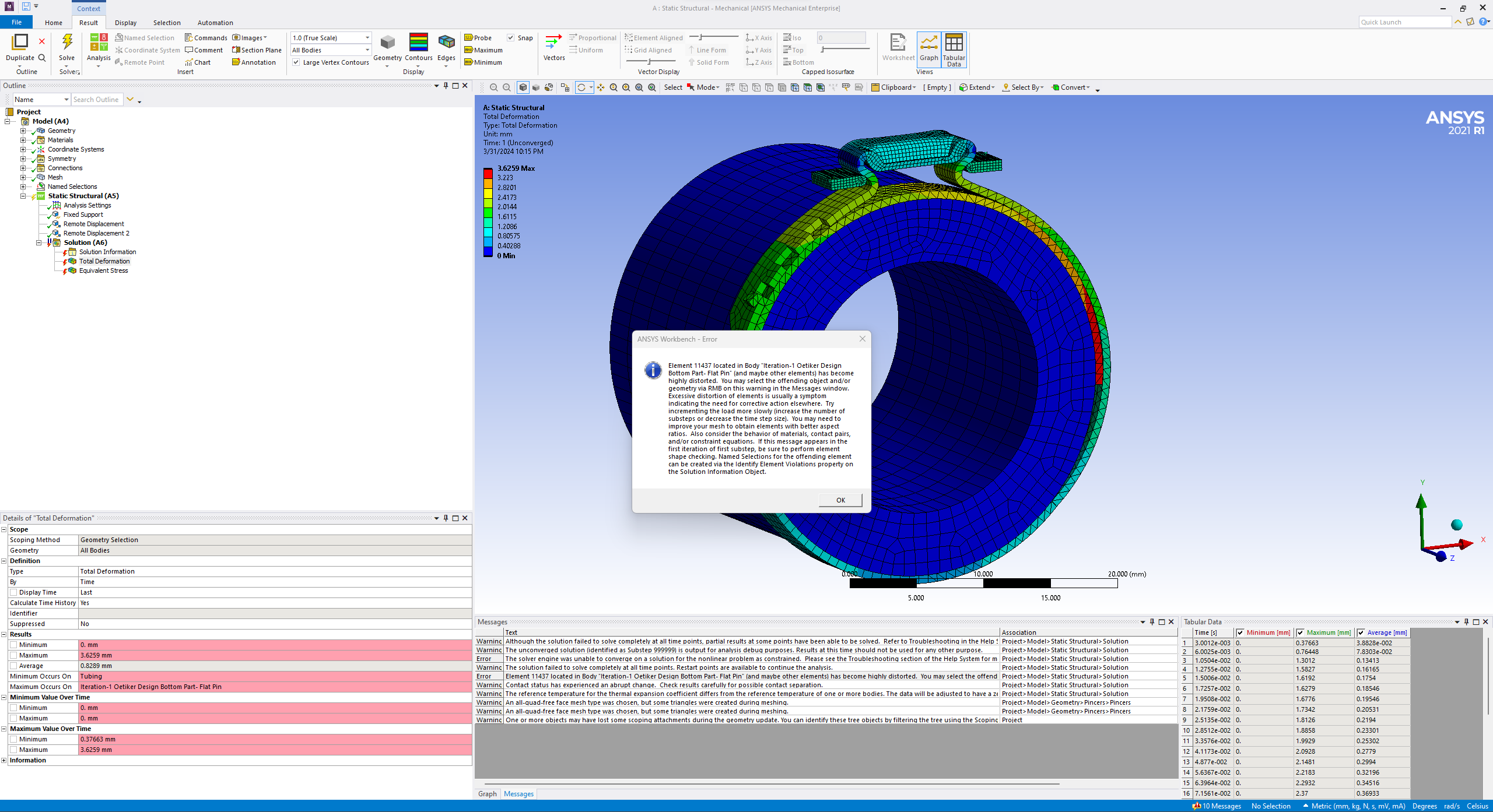
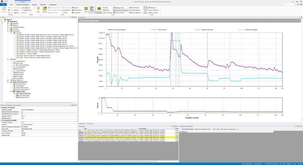
We have finally achieved the correct simulation. Clamp simulation. Thank you very much for your support! I have created another model file and run the analysis without changing the young's modulus. I have got the below two ERRORS. Do you think these are significant errors or we can ignore?
-
April 1, 2024 at 10:26 am
peteroznewman
SubscriberAll the steps that were computed are valid. The simulation nearly got to the end time, so if that is good enough, you can ignore the small amount of the simulation that did not compute.
If you want the simulation to converge to the End Time you specified, remesh and put more than 1 element through the thickness between the arrows.
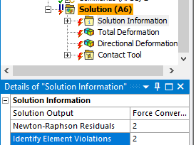
Under the Solution Information folder, type a 2 in the bottom two rows shown below. After a Solve, the highly distorted elements will be in a Named Selection, making it easy to see where in the model the elements with the error are located. You can improve the mesh in that area.
The error suggests to increment the load more slowly. Make the Analysis Settings a 2 step analysis where step 1 has an end time of 0.9 since it converges up to that point, and the new step ends at 1.0 but the Step Controls for step 2 will have an Initial and Minimum number of substeps of 50 and a Maximum of 1000. That and the better mesh will help it converge to the End Time of 1.0 You also have to edit the load, which is probably the displacement of the pincers and make step 1 be 90% of the original displacment, while step 2 has the original displacement.
-
April 10, 2024 at 2:38 pm
Sri Harsha Kallakuri
SubscriberHello Peter,
Sorry for the trouble. Unfortunately, I have lost the previous solved model because of a .rst file error. I have lost the file before even implementing the suggestions you have given. I have rebuilt the model as it is. But this time it is not converging at all. I have tried reffering to some online sources to understand the convergence errors but I couldnt understand the root-cause for this. Could you please help.
-
April 28, 2024 at 6:51 pm
Sri Harsha Kallakuri
SubscriberHello Peter,
I hope you are doing well. Unfortunately we are unable to progress anymore further on getting a converged solution of the clamp simulation. The contact between the pincer and the clamp ear is not getting recognized. (Contact slipping) I would like to seek any professional help. Could you please guide us with any sources where we can get consultation?
Thank you
-
April 28, 2024 at 10:08 pm
peteroznewman
SubscriberSorry that progress has stalled. Start by asking at the local vendor selling Ansys products in your region. You might find some other consultants through a Google search.
-
April 28, 2024 at 11:53 pm
Sri Harsha Kallakuri
SubscriberThank you! We are so grateful for your help so far. We wouldn't have reached this far in our project without your insights.
-
- The topic ‘Confused on Boundary conditions’ is closed to new replies.


-
4949
-
1639
-
1386
-
1242
-
1021

© 2026 Copyright ANSYS, Inc. All rights reserved.

