Electronics

Electronics

Topics related to HFSS, Maxwell, SIwave, Icepak, Electronics Enterprise and more.

Conflicting results in Transient analysis

    • user deleted
      Subscriber

      A coul and magnet are modelled the same as transient translational motion problem 7.3 v15. One model has a north facing pole and another model has a south facing pole. The coil has a terminal and the excitation is an external with a winding, resistor and earth. When modelled with the coil terminal current in the same direction as the current density it is noted that the phase relationship between current and induced voltage is 180° out of phase with the north facing magnet and in phase with the south facing magnet. According to the Curl rule then the current and current density are defined. Initially the magnet is approaching the coil. In the case of the north or south facing magnet an induced current is created causing the magnetic field in opposition to the approaching magnet. In the expected result we would find that phase relationship between induced voltage and current according to Maxwell's law would be 180° out and in relationship to Lenz's law it would be in phase. We cannot find any indications as to whether Maxwell or Lenz's law is used to determine the induced voltage and we take it that J is conventional current which is the movement of the positive charge carriers. Because of the results of the north and south approaching magnet being different we cannot determine any further. Please provide assistance. You could inform us that:

      1) J is positive charge carriers or negative

      2) Whether the induced current uses Lenz's law or not

      If you require drawings please do not hesitate to notify us. As we have noted that you don't open any attachments. Then please let us know how to provide.

    • NKC
      Forum Moderator
      Hi @igorgordeev I don't have access to the problem 7.3 V15 you are talking about. Please provide some screenshots of the problem to interpret it better.
      Provide some screenshots of your model aswell.
      Please use the image option and not the Attachment option while sharing the screenshots.
      Regards Navya
    • user deleted
      Subscriber
      Magnet moving upward with velocity through a coil
      This is the external circuit for the project
      I and J are in the same direction
      North facing upwards
      This is the result. It due to J is positive and induced voltage is negative. I and J are in the same direction
      This time the magnet direction is south pole upwards and I and J are in the same direction
      This is the result. It(current) due to J is in the same direction as the voltage.
      The expected result is that the direction of I and J for the north versus the south pole would be opposite and that the induced voltage would be opposite of the current in both instances. This would then follow Faraday's law
      Cannot determine by the conflicting results of the induced voltage, I and J whether the Ansys Electronics program is using Faraday's law or Lenz's law. Can you help to determine this please


    • user deleted
      Subscriber

    • user deleted
      Subscriber
      For current and voltage the meter indicates electron flow. The current and voltage are in the same direction. This behaviour should be represented in Ansys. In the results for south pole upward facing the current due to J (field calculator) is in the same direction as the voltage and the current through the coil winding (external circuit) is 180┬░ out of phase.

    • user deleted
      Subscriber


    • NKC
      Forum Moderator
      Hi @igorgordeev It's not very clear to me what exactly is the question you have. But from what I understand, below is the response.
      The J field plot is the current density (current/Area) so it will be in the same direction as that of the current.
      Ansys Maxwell uses Maxwell's equations for solving the fields and induced quantities.
      Regards Navya
    • user deleted
      Subscriber
      We have send the results showing current and J in the same direction (we understand Ansys uses I as conventional current, please verify) so that is positive charge flow. The results for north facing and south facing poles into the coil contradict one another ( in the south we have It and induced voltage in the same direction and the current is opposite. This is with the coil terminal pointing in the same direction as J) (in the north pole facing It and current are the same and induced voltage is opposite. This is with the coil terminal pointing in the same direction as J) THIS IS NOT POSSIBLE. Also placement of the coil with dot symbol interchanged makes no difference to the result. The reason why the dot brackets current flow is given as to allow opposite MMF production depending on whether the coil is physically rotated. That is north pole facing coil on one side will give say positive current and negative current when approached on the opposite side of the coil. So these are the two issues. Please refer to prior results submitted and note the current due to current density (It) and induced voltage. Conversely make a model and simulate with both north and south pole and look to the results. If this is not working correctly then coupled inductors and transformers may also not be current, we haven't studied this yet. If possible can we please have a contact with a technician or professor who is working with you. This appears to be a fault in the software. Please supply some detail for more private conversation.
    • HDLI
      Ansys Employee

      Here is some information.
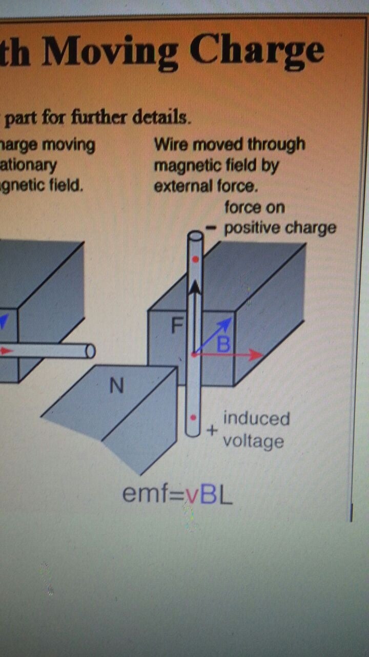
      1).Induced current direction
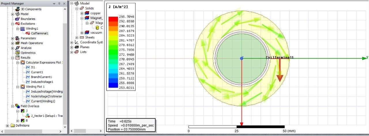
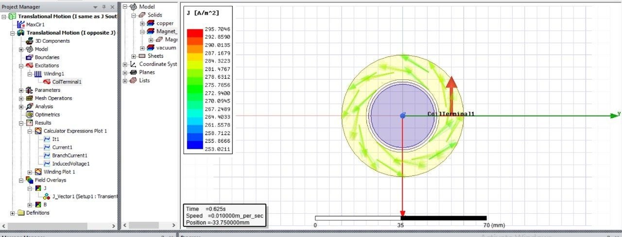
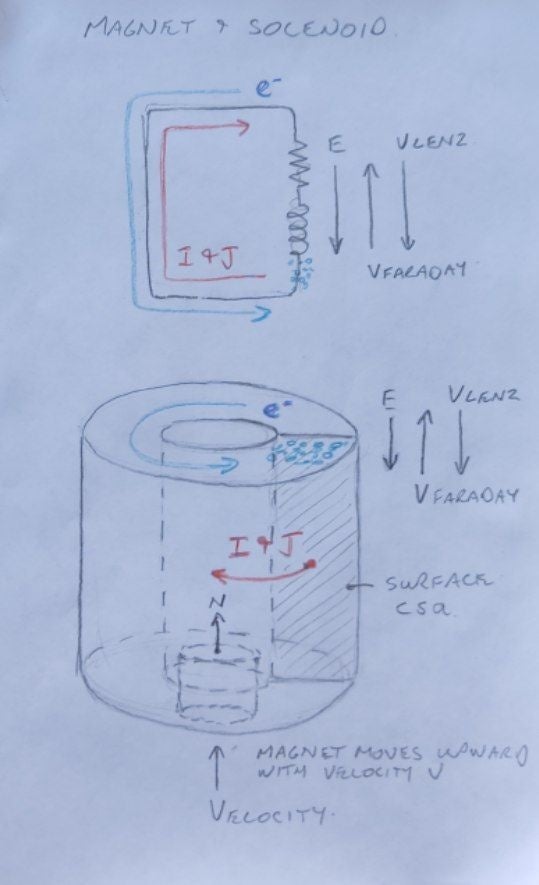
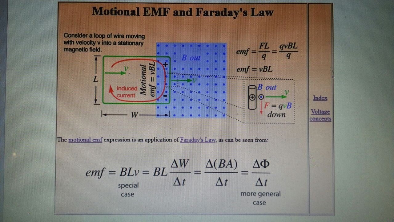
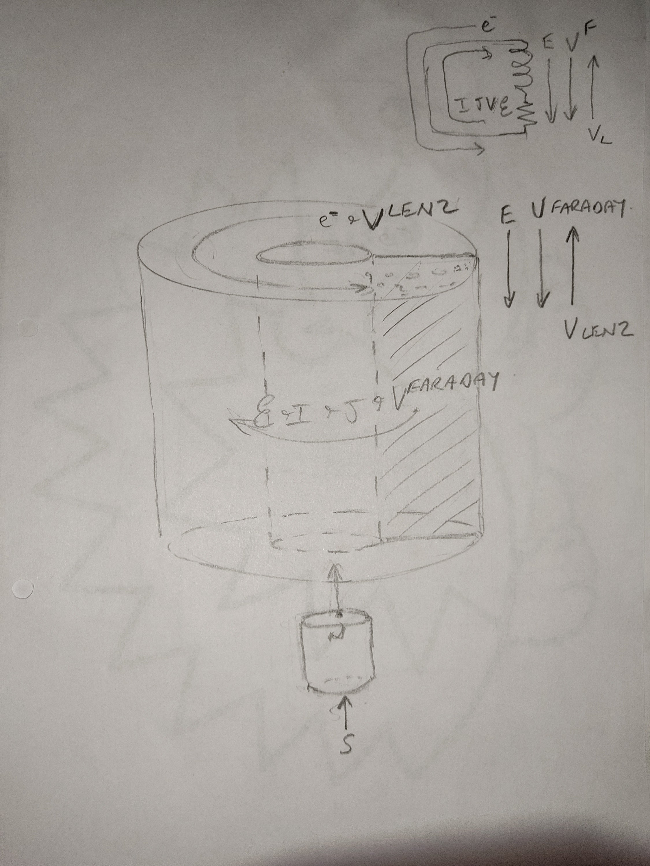
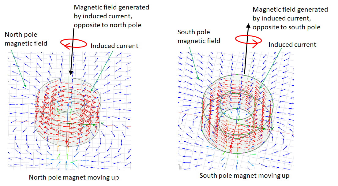
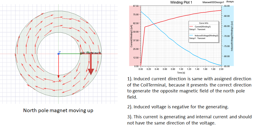
      Please see below. The induced current follows the LentzÔÇÖs law exactly. Please use right-hand rule to determine the current direction and for either of north pole or south pole moving of this simulation, the magnetic field created by the induced current opposes changes in the initial magnetic field.
      2). CoilTerminal direction
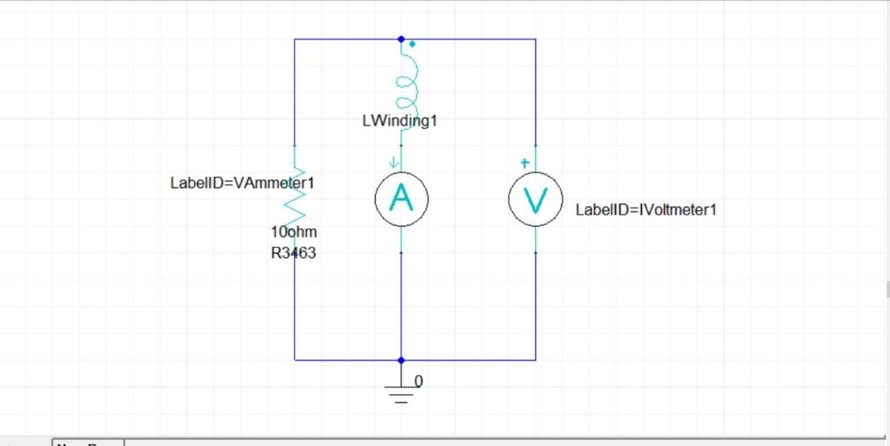
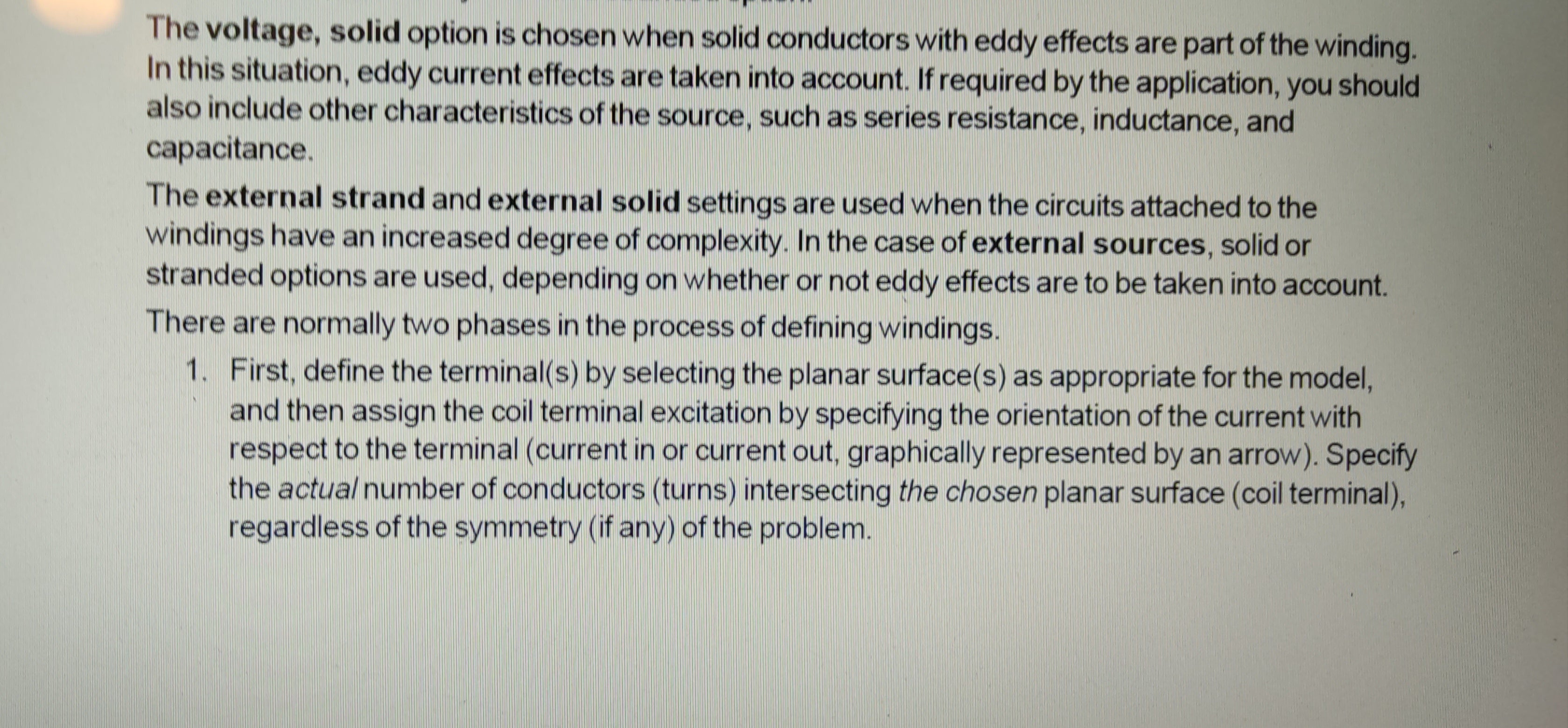
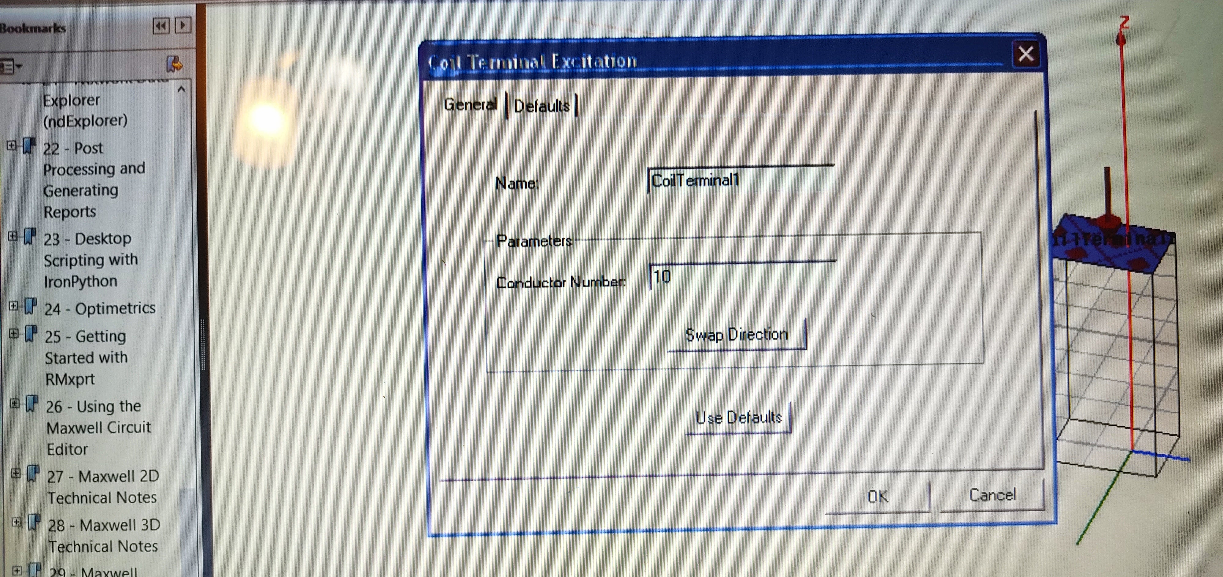
      We use ÔÇ£externalÔÇØ as winding type and it presents the BackEMF direction (voltage direction), not for current, because we use external circuit.
      3). Power generation in the simulation
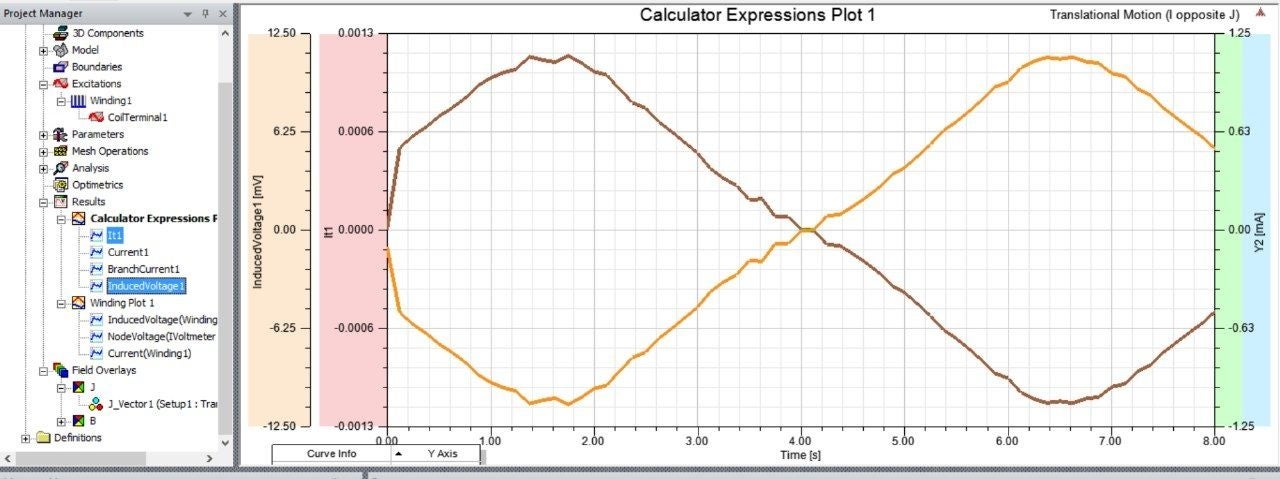
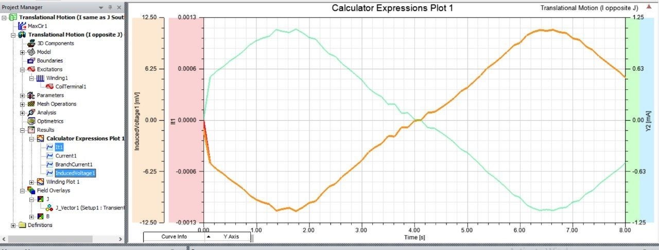
      In this simulation, we calculate induced current and voltage with magnet motion, and it is generating operation. Thus, the direction of the induced current is always opposite to the voltage direction to present the power generation. This current is generating and conventional internal current.


      Thanks
      HDLI
    • user deleted
      Subscriber
      Thank you very much. Understood, all good. It is nice to know that the coil terminal is indicative of induced voltage. Please note in response to information provided.
      1) Coil terminal external circuit gives direction of induced voltage (BackEMF)
      2) Coil terminal and induced voltage are in the same direction as per your figure
      3) The graph results indicate a 180┬░ phase shift between I and induced voltage
      4) This indicates Faraday's law: EMF=N*change in flux ├À change in time. On the other hand Lenz's law : EMF = -(negative) N * change in flux ├À change in time.
      5) Earlier we showed a meter and coil (photo). When the magnet approaches the coil both I and induced voltage have substantially the same phase (phase is dependent upon the inductance) 'Yes' the meter indicates electron flow
      6)PLEASE SHOW THE FIGURE FOR SOUTH POLE AND ITS GRAPH RESULTS. We really appreciate your time in this matter.

    • user deleted
      Subscriber
      Please note within the text "...assign the coil terminal excitation by specifying the orientation of the current with respect to the coil terminal..." (page 2931 Maxwell Help)


    • user deleted
      Subscriber
      The result in output (power) from the coil is imaginary. If you connect the output of the coil to a transformer (all in external circuit) then measure the output of transformer there is no power.
    • user deleted
      Subscriber
      Hello could you also graph current due to current density(field calculator). Please consider the following....the coil terminal is a thin section removed from the coil and a resistance is placed there so there is still a closed loop. The magnet is moving upward and is producing a force on the electrons which cause a depletion on one side of the section and excess electrons on the other. A field E is created across the resistor which is from positive to the excess of negative electrons and a voltage which is from excess negative electrons to positive. The reason that this occurs is because the magnet is moving and continues while a force on the magnet is maintained causing the movement of electrons. The reason to have Lenz law (voltage opposite to the sign of the voltage due to Faraday law) is so that current and voltage are in phase ....if this were not so then generators would not work. Please refer to the drawing of the coil magnet and circuit submitted earlier. I connect a meter (set for DC) to a coil and bring a magnet towards it...the sign of both current and voltage are the same if they were 180 degrees apart then the signs would be opposite ......please try it.


    • user deleted
      Subscriber
      Please we need to see the result of graphs for north and south pole plotting I due to J , current and induced voltage
    • user deleted
      Subscriber

    • user deleted
      Subscriber
      When this formula is used particularly for south pole facing upwards then the induced current due to J and current do not match.
      I have considered your comments and believe this is what you are trying to say. As the coil is not a closed loop then electric field and voltage can be determined across the windings. The best indicator of the correct notation is still by using a voltmeter. This method determined that the sign of current and voltage must be the same and not opposite (180┬░ phase difference).
Viewing 15 reply threads
  • The topic ‘Conflicting results in Transient analysis’ is closed to new replies.