-
-
March 6, 2024 at 7:30 pm
Ming Loon Lee
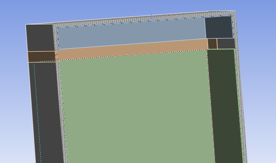
Subscriberfig 1 (ansys data)
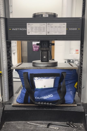
fig 2: experiment data
Hi, i am currently working on a project of dropping a container off a drone. The container several layers (outer layer, inner layer and the zipper) in it and i have all the material properties obtained from the lab and inserted into the engineering data (includes Multilinear plasticity). Now, i want to validate the model by compressing it and compare to the compression test from the lab. However, the compression static test could not converge fully.
Error The solver engine was unable to converge on a solution for the nonlinear problem as constrained. Please see the Troubleshooting section of the Help System for more information.
Analysing part of the result that converged, the force is very much larger than the experiment from the lab. Can anyone help me on this please. thank you -
March 7, 2024 at 2:29 pm
Armin
Ansys EmployeeHi Ming,
Could you provide a picture of the setup of the model? Like how compression is applied in the simulation versus actual compression test in the lab?
Also, could you describe how you considered interactions between the layers of the container? Did you assume bonded contact?
-
March 8, 2024 at 5:52 pm
Ming Loon Lee
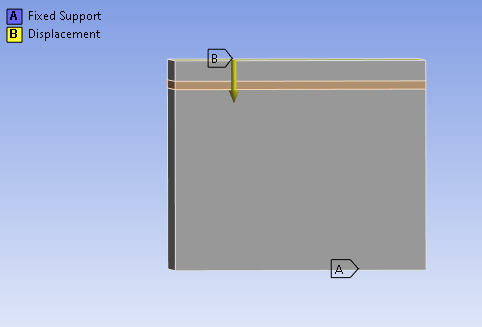
SubscriberHi Armin, thanks for your reply. i apply a displacement on top of the box and a fixed support at the base. Yes, the layers are all in bonded contact. The displacement speed in the experiment is 100mm/min, how should i input that in the analysis? And also is it because the material properties defined are all from tensile test data and not compression. Because the outer layer is a type of nylon fabric.
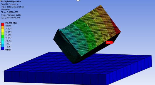
If so, is it possible to input two types of data (tension and compression) to define the material? The final objective is to perform the drop test model and the purpose of this compression test is to verify that model. Here is a picture of the drop test model.
-
March 11, 2024 at 1:41 pm
Armin
Ansys EmployeeThanks Ming.
My impression is that your model might be over-constrained compared to what happens in the actual compression experiment. Instead of using fixed support, try modeling the compression plates at the top and bottom then define contact pairs with appropriate friction coefficients (this is easier in Explicit Dynamics and Ansys LS-DYNA). Then try comparing your deformation pattern with that of the experiment.
You are right and compression response of some materials are different than tensile response. However, if you'd like to consider this effect, the tension-compression asymmetry of the materials should also be characterized experimentally.
-
-
-
March 8, 2024 at 10:57 am
peteroznewman
SubscriberHi Ming,
An important feature of real parts is that they are not geometrically perfect. The sides are not perfectly flat, the edges are not perfectly straight, the parts are not perfectly aligned.
The CAD geometry you meshed is geometrically perfect. This can cause much larger forces to be found in simulation compared with what was measured on real parts in the lab.
The corrective action is to introduce geometric imperfection into the geometry prior to running the simulation. You can do that manually in CAD. You can do that by performing an Eigenvalue Buckling analysis and adding a small percentage of the buckled shape to the perfect geometry to make it imperfect.
-
March 8, 2024 at 5:55 pm
Ming Loon Lee
SubscriberHi peter, thanks for your reply. It is possible for u to guide me on how can i introduce geometric imperfection into the geometry, as I am new to Ansys.
And also is it because the material properties defined are all from tensile test data and not compression. Because the outer layer is a type of nylon fabric.
-
-
- The topic ‘Compression test’ is closed to new replies.


-
4678
-
1565
-
1386
-
1241
-
1021

© 2025 Copyright ANSYS, Inc. All rights reserved.


