General Mechanical

General Mechanical

Topics related to Mechanical Enterprise, Motion, Additive Print and more.

Compressing Two Springs and a Rubber Cup

    • mehdimechanic
      Subscriber

      During my solve procedure, i face these expression. 
      What does these expressions say about the convergence behavior?  What does this expression "  ESTIMATED TIME FOR ELEMENT  ... TO CHANGE STATUS IS  0.7166  " mean and how can treat?
       
       *** LOAD STEP     1   SUBSTEP    83  COMPLETED.    CUM ITER =    360
       *** TIME =  0.716609         TIME INC =  0.100000E-03
       *** ESTIMATED TIME FOR ELEMENT  ... TO CHANGE STATUS IS  0.7166   
       *** AUTO STEP TIME:  NEXT TIME INC = 0.10000E-03  UNCHANGED


      I have another question, can a pre-stress(pre-load) be exerted to a self sketched spring? ( a geometry of spring is sketched in CAD programs and imported into ANSYS). If YES, how it can be?

      Thanks for the help in advance. 

    • peteroznewman
      Subscriber

      About those expressions in the solver output, I don't know what it means, but it is not requiring you to take any action, so I suggest you ignore that message.


      If you draw a spring in CAD, you must draw it in the unstressed state. Say the free length of a spring is 50 mm, and it will be stretched to 60 mm when it is installed in a structure. You must draw it at 50 mm.  If it is a coil spring, it would be best if you create a 3D curve in SpaceClaim and convert that to a beam.  You might have a structure that has two points that are 60 mm apart. Draw the spring starting at one side and leave a 10 mm gap on the other side.


      In Mechanical, use a spherical joint to connect one end of the spring to the coincident point on the structure, and use a translational joint between the end of the spring and the other point on the structure. Add a joint load on the translational joint for a 10 mm displacement. That will load the spring into the structure.

    • mehdimechanic
      Subscriber

      Thank you for quick answer.
      Can the geometry import from cad software for example Catia and be converted to the beam? why should i convert it to beam?
      How should i input spherical joint and transnational joint?Could you please explain with more details?
      Actually the spring is connected to structures in both sides and should be compressed. to create pre-tension. Can your suggestion be used for this compressing pre-stress?
      thank you for your help

    • peteroznewman
      Subscriber

      Export a STEP file from Catia. Open that in SpaceClaim. You may be able to convert a coil spring into a beam if the cross-section is constant. You convert the solid model of a coil spring to a beam in order to reduce the size of the model so it solves in much less time.  If you succeed in this, you can save the SpaceClaim .scdoc file and attach it after you post a reply, then I can see your geometry.


      If you have a structure that will compress a 70 mm long spring into a 60 mm space, you can do so using the same process described above.  The problem with compression springs is that they can buckle.


      When you reply, say what version of ANSYS you are using and whether you have a Research license without limits or if you have the free Student license that has node limits.


      Maybe you could edit the Title of your first post and make it "Modeling Coil Spring in CAD"

    • mehdimechanic
      Subscriber

      actually my geometry contains far more parts.
      i will attach you the file to see.
      i have student license with node limits.
      my geometry contains a cup,two springs and a holder with a rubber.
      i should move the cup so that springs would compressed and also the rubber should compressed also.
      could please help me on the contacts between parts and how to compress parts?
      i tried rigid body motion for moving the cup and compressing all parts.
       

    • peteroznewman
      Subscriber

      You will have to simplify the model to keep it within the Student license node limits. You can't leave it all solid elements. The cup and holder could be rigid bodies.


      The springs could become line bodies and meshed with beam elements, or each coil spring could be entirely replaced with one spring element. It depends on the analysis goal.  What is the key response that you want to see most accurately represented in the solution?  What question do you want the result of the simulation to answer?


       I changed the Title of your Discussion.

    • mehdimechanic
      Subscriber

      The forces between contact parts, during compression, its diagram during time step and stress state of the parts is the final goal of simulation.
      how can i replace coil spring with one spring element?

    • peteroznewman
      Subscriber

      Do you know the spring rate of each coil spring, either by measurement or because a spring design program created them?  If you do, then you can type in the value of "k" into a spring element like COMBIN14.  Once end of the spring would be connected to a remote point at the center of the face of the cup and the other end of the spring would be connected to a remote point at the center of the face of the holder.  The small spring is connected to a different face of the cup but has a gap between the other end and the rubber face.  For that you would use a COMBIN40 spring element which supports a gap in the definition. Look these elements up in the ANSYS Help system.


      Here is how you enter those springs into the Mechanical model after you create a Spring under the Connections folder.


      If you do not know the spring rate of each spring, then create two small models where the only body in the model is one spring. Create a Fixed support at one end and a Displacement at the other end of the spring. Add to the Solution branch a Reaction Force probe. Now you can divide the force by the displacement to calculate the spring rate "k".


      Since the rubber cup geometry and the loads are axisymmetric, I recommend you convert this entire model to an axisymmetric model. An axisymmetric model requires a 2D radial slice of the geometry to be on the XY plane, with the Y axis as the axis of rotation and the slice to be on the positive X side of the Y axis.  If you do that, and use the single spring element for each spring as described above, you can just keep the Rubber and the Holder.  The rightmost face of the Rubber in the image above can be considered Fixed.  The Holder can have frictional contact (harder to converge but more accurate) or bonded contact with the Rubber.  The cup is left out of the model. Instead, the two nodes that represent the ends of the springs that touch the cup are given displacement inputs to compress the assembly.

    • peteroznewman
      Subscriber

      Here is an Axisymmetric model of the Rubber and the Holder being compressed 6 mm and the Reaction force to do that for a generic rubber material whose properties I made up.  You have to get your own hyperelastic material properties.


       ANSYS 2019 R2 archive attached.

    • mehdimechanic
      Subscriber

      Thank you for your patience and help.could you please upload the model which you solve in ANSYS? I think i need to know the contact assumption you have used for the solved model. and could you tell me how the force displacement diagram is created? Thanks in advance


      And i have another question. i want to exert the displacements in two steps.First step compressing rubber and after that, fix the compressed rubber from the yellow part and continue compressing springs. is it possible? i used displacements in two steps, but i can not handle it correctly since the rubber is not in its the initial state.

    • peteroznewman
      Subscriber

      Uploaded the ANSYS 2019 R2 archive of the Axisymmetric model above. You will see the Chart object and the Details window for how the chart was made.


      You can do any combination of loads in different steps. Just apply the loads in the order that you would physically do it to the parts.

    • mehdimechanic
      Subscriber

      How should i exert the displacement to fix the deformed rubber? should i give the displacement 6 in the second step ( after compressing the rubber 6 mm) or i should give 0 to keep it fixed? thank you for your help and kindness.

    • peteroznewman
      Subscriber

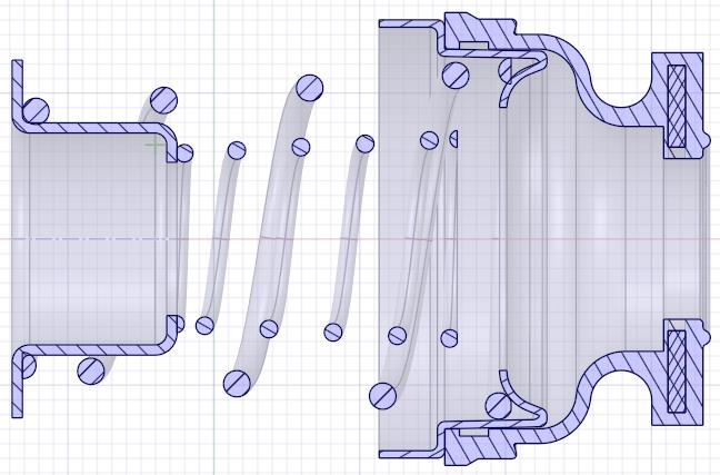
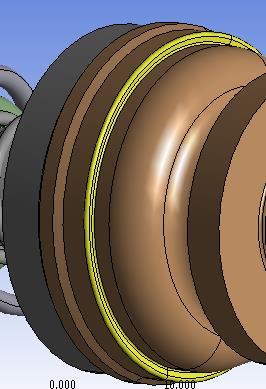
      The yellow part clamps the rubber to the holder by a radial displacement of the clamp. The clamp does this first, before any compression of the rubber boot in the axial direction. That would best be done by drawing a circle tangent to the rubber. Create a material for the clamp that has a Coefficient of Thermal Expansion.  Apply a Thermal Condition in Step 1 of the model and change the temperature by an amount that will cause the clamp to shrink onto the rubber.


      If the flat face at the small thick end of the rubber is considered to be a Fixed Support, and the Cup is moved axially toward the rubber, the cup has to move 14 mm axially, compressing the spring until the small spring gap to the rubber closes. This can be Step 2, then some more displacement occurs in Step 3 so the small spring will compress.


      1) What is the correct total axial displacement of the cup?


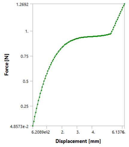
      2) Do you have the spring rates for each spring?


      3) Do you have the correct Material Properties of the Rubber? I just made up some properties.


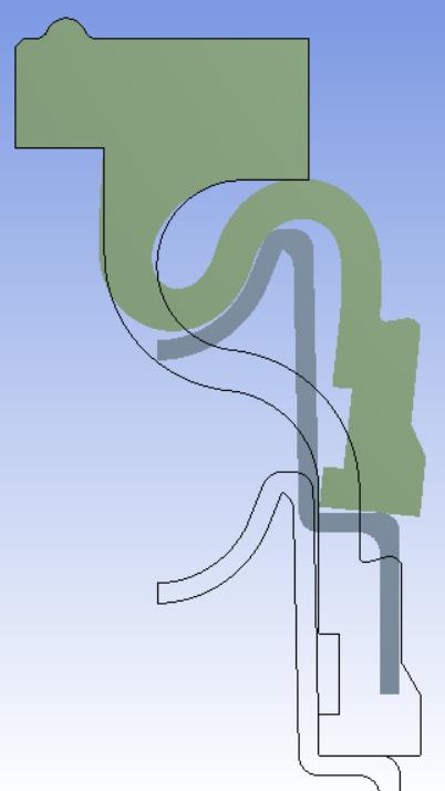
      With that information, you can finish the Axisymmetric model.  Moving the Holder by 6 mm was just my example, I don't think it is the correct amount. The correct amount of axial displacement of the large side of the rubber is determined by the balance of force between the spring and the rubber.  If the spring is higher rate, there will be more deformation in the rubber, if the spring is lower rate, there will be less deformation in the rubber.

    • mehdimechanic
      Subscriber

      Thank you for the help


      1.The axial displacement of the cup is 18.3 mm so that the spring will be in fully compressed state.


      2. The big spring constant is 4.4 N/mm and the small spring constant  2.2 N/mm


      3. I attach the stress- strain relationship of the hyper elastic material.


      actually the cup is connected to a shaft. and shaft moves and compresses the assembly.


      thank your for all the attention and help. 

    • peteroznewman
      Subscriber

      Great, now see if you can create a Hyperelastic Material using that data.


      Blog


      https://youtu.be/3bjCkvobbpY

Viewing 14 reply threads
  • The topic ‘Compressing Two Springs and a Rubber Cup’ is closed to new replies.