I am trying to create a nodal reaction force versus displacement for a composite laminate subjected to an applied displacement over a given length of time. The composite coupon is constrained at one end with an applied displacement at the other end, as in a tension test. SHELL281 elements are used. The laminate is symmetric about the midplane and has 24 laminas. I am using progressive damage with the Hashin criteria. The laminate has a hole in the center.
What I am hoping to see is the drop in nodal reaction force at different points in the displacement due to the various layers becoming damaged at different times. I would expect to see something like the graph below.
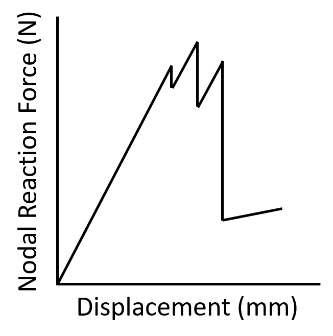
Is this the code I should be using to generate such a graph? Is there a way to select all the nodes at the constained edge and plot them in one graph like the picture above?
!PLOT NODAL REACTION FORCE VERSUS DISPLACEMENT AT NODE 5616
LAYERP26,1 !SELECT THE LAMINA
SHELL,MID !SELECT THE MIDDLE LAYER IN THE SHELL ELEMENT FOR RESULTS
RFORCE,3,5616,F,X,FX NODE 5616 !DEFINE VARIABLE #3 = X-DIRECTION REACTION FORCE AT NODE 5616
NSOL,2,5616,U,X,UX !DEFINE VARIABLE #2 = X-DIRECTION DISPLACEMENT AT NODE 5616
/AXLAB,Y,REACTION FORCE [N] !LABEL Y-AXIS AS "NODAL REACTION FORCE"
/AXLAB,X,DISPLACMENT [mm] !LABEL X-AXIS AS "DISPLACEMENT"
PLVAR,3 !PLOT VARIABLE #3 AS Y
XVAR,2 !PLOT VARIABLE #2 AS X
The node I chose is a node at the periphery of that hole that becomes damaged during the applied displacement. Is this a correct choice of node given what I am trying to do?
Should I be using a stress versus strain graph instead?
Thank you!


