

-
-
January 29, 2022 at 4:24 am
srutheesh
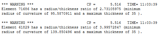
SubscriberHi, Im doing an ACP analysis for Carbon Fiber winding. I came across error messages as follows;
January 31, 2022 at 2:39 pmAshish Khemka
Forum Moderator
Please see if the following post helps you:
Element radius/thickness ratio warnings during solution? ÔÇö Ansys Learning Forum
Regards Ashish Khemka
January 31, 2022 at 3:06 pmManish Dubey
Ansys Employee
If the initial shape of the model is curved, then theradius/thickness ratiois important because the strain distribution through the thickness departs from linear as the ratio decreases. Some shell elements, such asSHELL181andSHELL281, use an advanced element formulation that accurately incorporates initial curvature effects.
The curved-shell formulation is automatically disabled for excessively thick and curved structures with an r / t ratio below 5 / 6, where r is the radius of curvature measured at shell mid-plane and t is the total shell thickness.
For Shell181 elements (linear shell), you can use the advanced curved-shell formulation (Keyopt 5 = 1) and for this you probably need to set that Keyopt using MAPDL commands in a Command Object.
"When KEYOPT(5) = 1, the element uses an advanced formulation that incorporates initial curvature effects. The calculation for effective shell curvature change accounts for both shell-membrane and thickness strains. The formulation generally offers improved accuracy in curved shell structure simulations, especially when thickness strain is significant or the material anisotropy in the thickness direction cannot be ignored, or in thick shell structures with unbalanced laminate construction or with shell offsets. The initial curvature of each element is calculated from the nodal shell normals. The shell normal at each node is obtained by averaging the shell normals from the surroundingSHELL181elements. A coarse or highly distorted shell mesh can lead to significant error in the recovered element curvature; therefore, this option should be used with a smooth, adequately refined mesh only. To ensure proper representation of the original mesh, a nodal normal is replaced by the element shell normal in the curvature calculation if the subtended angle between these two is greater than 25 degrees."
Also, you can use SOLSH190 for simulating shell structures with a wide range of thickness (from thin to moderately thick). The element possesses the continuum solid element topology and features eight-node connectivity with three degrees of freedom at each node: translations in the nodal x, y, and z directions.
References:
[1]SHELL181 (ansys.com)
[2]5.2. Shell Elements (ansys.com)
[3]SOLSH190 (ansys.com)
I hope this helps.
Thanks
Manish
March 15, 2022 at 6:12 amSubscriberDear
Thank you for your response.
Sorry, I took long to reply as I was busy with the project.
The link you provided is useful information and thank you for the same.
BR
Srutheesh S
Viewing 3 reply threads- The topic ‘COMPOSIT ANALYSIS – MESHING ISSUES AND ERROR MESSAGES’ is closed to new replies.
Ansys Innovation Space Trending discussions
 Top Contributors
-
peteroznewman
 3892
3892 -
scabo
 1414
1414 -
Dennis Chen
 1241
1241 -
javat33489
 1118
1118 -
Shyam Prasad V Atri
1015
Top Rated Tags
© 2025 Copyright ANSYS, Inc. All rights reserved.
Ansys does not support the usage of unauthorized Ansys software. Please visit www.ansys.com to obtain an official distribution.
-


The Ansys Learning Forum is a public forum. You are prohibited from providing (i) information that is confidential to You, your employer, or any third party, (ii) Personal Data or individually identifiable health information, (iii) any information that is U.S. Government Classified, Controlled Unclassified Information, International Traffic in Arms Regulators (ITAR) or Export Administration Regulators (EAR) controlled or otherwise have been determined by the United States Government or by a foreign government to require protection against unauthorized disclosure for reasons of national security, or (iv) topics or information restricted by the People's Republic of China data protection and privacy laws.


